P.J.Napier
NRAO, Socorro, NM.
8 September, 1995
ABSTRACT Two potential MMA antenna designs are compared with respect to sensitivity, polarization purity, field-of-view and sidelobe level. Under conditions of very low atmospheric opacity and receiver noise temperature the offset reflector design has better sensitivity than the minimum blockage conventional design at about the 10% level. The offset design has poorer performance than the conventional design in the areas of polarization purity and field-of-view. If these problems with the offset design are cured using additional reflectors in the optics path then the sensitivity advantage of the offset design is lost.
The MMA Antenna Working Group is currently comparing two significantly different designs for the MMA antenna. One design is an offset reflector on a slant-axis mount (Cheng, 1994). The other design is a more conventional symmetric reflector on an azimuth-elevation mount. This latter design is based on the BIMA antenna design whose key features include a minimum blockage subreflector support structure with feedlegs extending to the edge of the dish and a very simple and clean optics design (Lugten, 1995). In this report we compare the performance of these two designs for those electromagnetic parameters which could be expected to be significantly different between the two. Sensitivity, polarization, field-of-view and sidelobe level are examined. Comparison of other properties such as structural performance and cost will be presented elsewhere.
Here we present a simplified comparison of the sensitivities of the two antenna designs. We will compare the ratio OnAxisGain/System Temperature (G/T) for the two designs. The antenna design selected for the MMA will be used for the entire 25+ year life of the instrument, but the receivers will certainly be improved during this period. Therefore this analysis is performed for the best receivers believed achievable. Similarly, we would like to know how the antenna design influences sensitivity during the best observing conditions so very low atmospheric opacities are used here. The analysis is performed for two frequency bands, 86 GHz and 230 GHz, each at the two elevation angles 90 and 30 degrees.
ASSUMPTIONS
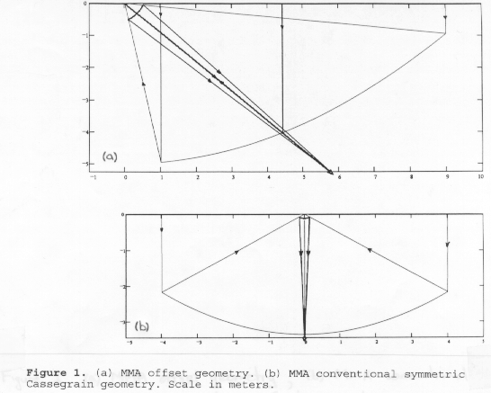
The results of this G/T analysis are completely determined by the assumptions made about the performance of the two designs. Here the assumptions, which are based where possible on calculations or experience at existing instruments, are clearly defined so that readers can change them if they wish. For both antenna designs a very clean optics path, similar to that used on the BIMA antennas, is assumed. Thus the receiver is located at the Cassegrain focus with no tertiary reflectors and the feed is looking directly at the subreflector, as shown in Figure 1.
Relative Gain:
As a measure of relative gain we will use aperture efficiency which we will assume to be the product of the four factors spillover, taper, surface and blockage efficiency. Assume that the product (spillover efficiency) x (taper efficiency) is the same for both designs and a reasonable value for this product, from measurements on the BIMA antenna (Lugten, 1994), is 0.81 (this value also includes an allowance for some small miscellaneous effects such as panel gaps). The surface efficiency is also the same for both designs and for a 25 micron rms surface accuracy the Ruze equation gives values of 0.99 and 0.94 at 86 Ghz and 230 Ghz respectively. The blockage efficiency for the offset design is 0.997 assuming a 30 cm diameter hole through the middle of the main reflector (large enough for a 3x3 feed array at about 150 GHz). For the minimum blockage conventional design the blockage efficiency is 0.96. This latter value results from 1.9% blocked area under the quadrupod legs and 0.1% central blockage due to the F/12 (30 cm diam.) subreflector shown in Figure 1 (remember that efficiency loss is approximately two times the fractional area loss). The 1.9% quadrupod blockage is a little higher than the 1.43% tripod blockage achieved on the BIMA antenna because the MMA requirements for subreflector nutation and high pointing and phase stability demand a more robust subreflector support. The total aperture efficiencies listed in Table 1 are the appropriate products of the individual factors; thus at 230 Ghz the conventional design has an efficiency of 0.81x0.94x0.96=0.73. This is consistent with efficiencies measured on the BIMA antennas (Lugten,1994).
Later in this report it is noted that the offset design has reduced performance in the areas of field-of-view and polarization purity. If this performance reduction is considered unacceptable then the only currently known cures for these problems require the addition of two reflectors in the optical path (Napier, 1994) . Thus, as a second case for the offset antenna the impact of adding two additional reflectors is included. It is assumed that each additional reflector will reduce efficiency by 0.5% and 1% at 86 Ghz and 230 Ghz respectively. These total losses are reasonable when the effects of surface roughness, surface resistive loss, diffraction and spillover are considered and are consistent with values adopted by the MMA Receiver Working Group.
Receiver Temperature (Trx):
Assume that best possible receivers have Trx equal to 2*h*f/k double sideband. This has been adopted by the MMA Receiver Working Group as a feasible goal. This gives values of 8.3K and 22.1K for 86 and 230 GHz respectively.
Design    f      Elev.   Rel     Trx     Tant    Tatmo   Tmbg    Tsys    G/Tsy   G/T


Type      (GHz)  (deg)   Gain G  K       K       K       K       K                 Ratio


Convent-      86      90    0.77     8.3     5.5     1.6     1.1    16.6   0.046

ional         86      30    0.77     8.3     5.5     3.3     1.1    18.4   0.042

             230      90    0.73    22.1     5.5     6.5     0.2    35.2   0.021

             230      30    0.73    22.1     5.5    13.0     0.2    42.8   0.017


Offset        86      90    0.80     8.3     4.0     1.7     1.1    15.2   0.053    1.14

No            86      30    0.80     8.3     4.0     3.2     1.1    16.8   0.048    1.14

Tertiary     230      90    0.76    22.1     4.0     6.8     0.2    33.9   0.022    1.08

             230      30    0.76    22.1     4.0    12.6     0.2    40.8   0.019    1.09


Offset        86      90    0.79     8.3     7.0     1.7     1.1    18.1   0.042    0.91

Two           86      30    0.79     8.3     7.0     3.2     1.1    19.6   0.040    0.95

Tertiaries   230      90    0.75    22.1    10.0     6.8     0.2    40.1   0.019    0.90

             230      30    0.75    22.1    10.0    12.6     0.2    47.1   0.016    0.93
Table 1. Results of G/T Comparison
Antenna Temperature (Tant):
This is noise due to spillover, diffraction, scattering and resistive loss. Tant measured on the BIMA antenna is about 5K of which 1.5K is estimated to be due to feed leg scattering to the ground (Lugten, 1994). For the MMA conventional design we will increase this scatter contribution by the ratio of the blocked areas to give 1.5x1.9/1.43=2K for a total antenna contribution of 5.5K. For the offset design the scatter contribution should be significantly reduced; we will guess 0.5K since there is one feed leg instead of four. Assuming that contributions to Tant other than scattering are the same for both designs then gives a total antenna contribution of 4K for the offset design.
When additional reflectors are added to the optics path we will assume that all of the lost power is terminated at 300K, giving additional noise contributions of 1.5K and 3K at 86 GHZ and 230 GHz respectively for each additional reflector.
Atmospheric Temperature (Tatmos):
Results from the first four months of monitoring on the site at 5000 m in Chile suggest that 225 GHZ zenith opacity is below 0.025 for approximately 10% of the time (NRAO, 1995). We will assume this opacity value and an effective sky temperature of 260K, giving a zenith noise contribution of 6.5K at 230 GHZ. For the conventional design this zenith contribution is multiplied by sec(zenithangle) to determine Tatmos at lower elevations. The situation is modified slightly for the slantaxis mount because the power from the feed which spills past the subreflector is always looking through the atmosphere at 45 degrees elevation, independent of the zenith angle of the main beam. This is a minor effect because only 10% of the power spills past the subreflector, but it has been included in the calculations. The opacity at 86 GHZ is assumed to be 1/4 of the 230 GHZ opacity, as predicted by atmospheric model calculations (Schwab and Hogg, 1989).
Microwave Background Noise (Tmbg):
Use Planck's Law (not RayleighJeans) to determine the effective noise temperature of the noise from the microwave background. Tmbg = 1.1K and 0.2K at 86 GHZ and 230 GHZ respectively.
Total System Temperature (Tsys):
Tsys is the sum of the four noise terms above, increased by the factor (1 + total opacity) to give an "outside the atmosphere" equivalent system temperature.
RESULTS:
The results of the calculations are given in Table 1. The last column gives the ratio of the G/T for the offset design to the G/T for the conventional design. In summary, under the assumptions made above, the offset design is about 10% more sensitive than the conventional design. This sensitivity advantage is lost if two tertiary reflectors are added to the optics path to cure the polarization and field-of-view problems. Note that the analysis presented has tended to maximize the difference between the different designs because, by assuming extremely low noise contributions from the atmosphere and the receiver, the effect of the small differences in antenna noise contributions is enhanced. With less sensitive receivers or higher atmospheric opacity the difference between antenna designs would be less.
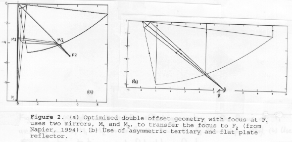
The polarization properties of the offset design (known as an Open Cassegrain geometry)have been discussed previously and some improvement methods have been suggested (Napier, 1994). In summary, the asymmetric geometry gives rise to a beam separation (squint) of 0.14 beamwidths between opposite circularly polarized beams or -22dB cross polarized sidelobes in the case of linearly polarized feeds. One way to correct the polarization is to use an optimized double offset geometry and two additional flat plate reflectors as shown in Figure 2. A second way to correct the problem is to insert an asymmetric tertiary mirror and an additional flat plate reflector to bring the beam down into the receiver cabin as shown in Figure 2. Since both of these solutions effectively convert an asymmetric geometry into a symmetric one, these solutions will also correct the field-of-view problem discussed below. J. Payne and D. Emerson have suggested a simple solution to the beam squint problem with circularly polarized feeds. They point out that in the focal plane the beam squint is equivalent to separated focal points for the two circular polarizations. If there are separate feeds for the two circular polarizations then the beams can be made coincident by locating each of the feeds at the correct focal point. Unfortunately this approach will not correct the field-of-view problem and for linearly polarized feeds will actually introduce a beam squint. Another possible solution to the polarization problem is to specially shape both the primary and secondary reflectors. This possibility is still being studied and is discussed further in Section 4 below. At present it does not appear that reflector shaping is an adequate solution for the polarization problem.
If the conventional design uses a perfectly symmetric Cassegrain geometry it will provide essentially perfect polarization performance with the ultimate polarization purity being determined by the feed and polarizer rather than by the antenna. If a slightly asymmetric geometry is used, for example as in the BIMA antenna where feeds are translated slightly off-axis to avoid the need for a rotating tertiary reflector for band changing (Lugten,1994), then polarization performance will be degraded by a small amount. For example, measurements and calculations for the Bonn 100 m telescope (Fiebig et.al., 1991) show a separation of only 0.03 beamwidths between opposite circularly polarized beams when the beam is scanned by as much as 11 beamwidths by feed translation at the secondary focus. 0.03 beamwidths of circularly polarized beam separation corresponds to -40 dB cross polarized sidelobes for linearly polarized feeds . Correct choice of off-axis geometry can remove even these small effects (Eilhardt, 1994).
The field-of-view performance of an antenna determines how rapidly peak gain and sidelobe level degrades as the beam is scanned off-axis by translating the feed sideways in the focal plane. The MMA antenna requires reasonable field-of-view for several reasons: we wish to keep open the possibility of operation in the future with a focal plane array; as mentioned in the previous paragraph we may wish to use the BIMA scheme of using off axis feeds for band changing; there is a requirement for beam scanning using a nutating subreflector for total power stabilization. Here we will investigate the gain loss at the peak of the beam for 4.2 beamwidths of beam scan. This is the amount of scan present for the corner elements of a 3 X 3 focal plane array with three beamwidths separation between array elements. Provided the gain loss is not too large (a few x 10%), for the kinds of phase aberration considered here the gain loss will vary as the square of the number of beamwidths scanned.
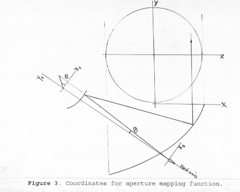
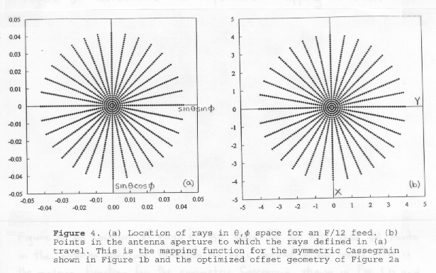
Many of the electromagnetic properties of a reflector antenna, such as polarization and field-of-view can be understood qualitatively by examining the mapping function which relates the feed pattern plane to the aperture plane. In Figure 3, if 2,N are spherical coordinates which define the direction of a ray from the feed and x,y are the points in the reflector aperture to which the ray travels, then the functions x(2,N) and y(2,N) provide the mapping of the rays from the feed to the aperture. For good polarization properties circular symmetry in the feed plane should map into circular symmetry in the aperture plane: thus rays with identical values of 2, which lie on circles in the 2,N plane as shown in Figure 4a, should map into circles concentric with the center of the aperture in the aperture plane, as shown in Figure 4b. Good field-of-view requires that the Abbe sine condition (Born and Wolf, 1975) be satisfied. In terms of the mapping function this requirement can be stated as
x(2,N) = c*sin(2)cos(N), y(2,N) = c*sin(2)sin(N) (1)
where c is a constant determined by the effective focal ratio of the optical system at the feed. The importance of condition (1) for good field-of-view can be easily understood as follows. When a feed is translated laterally in the focal plane the feed pattern has superimposed on it a linear phase gradient M(2,N) given by
M(2,N) = k*)x*sin(2)cos(N) + k*)y*sin(2)sin(N) (2)
where k=2B/8 and )x and )y are the feed displacements in the xs and ys directions respectively in Figure 3. The phase gradient, Ma(x,y), in the aperture plane is determined from (2) using the feed-to-aperture mapping function
Ma(x(2,N),y(2,N)) = k*)x*sin(2)cos(N) + k*)y*sin(2)sin(N) (3)
When (1) is satisfied (3) becomes
Ma(x,y) = k*)x*x/c + k*)y*y/c (4)
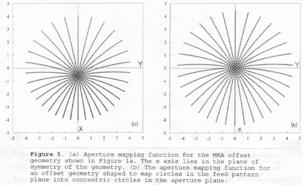
and the aperture phase is perfectly linear so that no deterioration in performance is caused by phase aberration. This is the case for both the symmetrical Cassegrain geometry of Figure 1b and the optimized double offset geometry of Figure 2a, the aperture mapping function for both of which is shown in Figure 4b. For these geometries it can be expected that field-of-view will be limited more by spillover increase than by phase aberration. For the uncorrected MMA offset geometry x(2,N) and y(2,N) can be derived from the basic formulas of the geometry (Cook, 1965) and the resulting aperture mapping function is shown in Figure 5a. Clearly the mapping function is highly distorted and loss of performance in both polarization purity and field-of-view can be expected. The origin of the circular polarization beam squint can be clearly seen in Figure 5a which shows that aperture field lines are rotated in a clockwise direction to the right of the plane of symmetry and anticlockwise to the left of the plane of symmetry. Furthermore, the amount of rotation increases with increasing distance from the aperture center. Remember that a rotation of circular polarization is the same as a phase shift then the rotation described in the previous sentence corresponds to a linear phase gradient which squints the circularly polarized beam off axis. The squint is in opposite directions for the two senses of circular polarization so oppositely polarized beams are separated on the sky. Field-of-view is poor. When aperture phase is calculated using (3) for 4.2 beamwidths of scan, and the radiation pattern is computed as the Fourier Transform of the complex aperture distribution, a gain loss of -2.6 dB is predicted for a -10 dB aperture illumination taper.
It has been suggested previously (Napier,1994) that a possible way to improve the polarization of the offset geometry is to shape the primary and secondary reflectors. This possibility has been investigated with assistance from L. Baker (Baker, 1995) who, starting with the MMA open Cassegrain geometry shown in Figure 1a, has synthesized a shaped geometry in which circles in the feed pattern plane (circles of constant sin(2)in Figure 4a) map into circles concentric with the aperture center in the aperture plane. The aperture mapping function for this geometry is shown in Figure 5b. Although circular symmetry is improved compared to Figure 5a, with only two reflectors to shape there are insufficient degrees of freedom to also remove the bending of the field lines which give rise to circular polarization beam squint. Calculations based on the mapping function shown in Figure 5b predict a circular polarization beam squint of 0.10 beamwidths total beam separation and field-of-view performance of -0.8 dB peak gain loss at 4.2 beamwidths of beam scan. A second shaped geometry will be synthesized which is optimized to minimize the field bending effects in the sense that straight spokes of constant N in Figure 4a map into straight spokes in the aperture plane. A final decision on the feasibility of shaping cannot be made until this additional work is completed, but at this time it does not seem likely that shaping will cure both polarization and field-of-view problems.
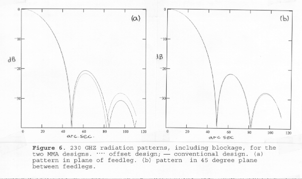
Since the blockage is significantly different for the two antenna designs we will investigate the effect of this difference on sidelobe level. Sidelobe levels and the degree to which the sidelobes are not circularly symmetric is potentially important for mosaicing observations. Here we will present a simplified analysis in which the offset design is modeled as an 8m diameter circular aperture distribution, with 0.30 m diameter central blockage, and an aperture distribution of the form b+(1-r2) where r is normalized aperture radius. Here b is chosen to give -10 dB illumination taper at the edge of the aperture. The minimum blockage conventional design is modeled in exactly the same way except that the effect of the 6.4 cm wide quadrupod shadows is included. The radiation patterns of these simple model aperture distributions can be evaluated analytically (Silver, 1965) and the results are shown in Figure 6. The difference between the two designs is small because blockage is so low. For the conventional design the first sidelobe is about 1 dB higher in the plane of the feed legs than it is in the 45 degree plane between the feed legs. This does not seem to be a significant difference since for the higher frequency bands, where mosaicing is most important, surface errors are likely to cause more loss of circular symmetry than this.
The offset reflector design has better sensitivity than the minimum blockage conventional design at about the 10% level, but only under conditions of extremely low atmospheric opacity and receiver noise temperature. The offset design has poorer performance than the conventional design in the areas of polarization purity and field-of-view. If these problems with the offset design are cured using additional reflectors in the optics path then the sensitivity advantage of the offset design is lost.
ACKNOWLEDGMENTS
I would like to thank the members of the MMA Antenna Working Group for assistance in preparing this report. Members of the Group include J.Cheng, D.Emerson, J.Lugten, J.Payne, J.Welch and D.Woody.
REFERENCES
Baker L., AExamples of Shaped Reflectors From a New Shaping Method@, IEEE Antennas and Prop. Int. Symp. Digest, New Port Beach, pp 1676-1679, 1995.
Born,M. and Wolf,E., Principles of Optics, 5th Edition, Pergamon Press, Oxford, 1975.
Cheng, J., "Homologous Offset Antenna Concept For the Millimeter Array Project", MMA Memo 110, March 1994.
Cook, J.S., Elam, E.M. and Zucker, H.,"The Open Cassegrain Antenna: Part I. Electromagnetic Design and Analysis", BSTJ, vol 44, pp 1255-1300, 1965.
Eilhardt,K., Wohlleben,R. and Fiebig,D., "Compensation of the Beam Squint in Axially Symmetric, Large Dual Reflector Antennas with Large-Ranging Laterally Displaced Feeds", IEEE-Trans AP, vol AP-42, pp 1430-1435, 1994.
Fiebig,D., Wohlleben,R., Prata,A. and Rusch,W., "Beam Squint in Axially Symmetric Reflector Antennas with Laterally Displaced Feeds", IEEE-AP Trans., vol AP-39, pp 774-779, 1991.
Lugten, J., AOptical Design and Performance of the BIMA Interferometer@, Proc. European Workshop on Low-noise Quasi-optics, MPIfR, Bonn, Germany, Sept., 1994.
Napier, P.J., APolarization Properties of an Open Cassegrain Antenna@, MMA Memo 115, May 1994.
NRAO, Results of opacity measurements available on the WWW at http://www.mma.nrao.edu/sites.html, 1995.
Schwab, F. R. and Hogg, D. E., AMillimeter-Wave Atmospheric Opacity and Transparency Curves@, MMA Memo 58, October, 1989.
Silver, S., Microwave Antenna Theory and Design, Chapter 6, Dover Pub., 1965.

mma@nrao.edu