This report compares two existing 8m designs for the Millimeter Wave Array (MMA) antennas. One is a conventional elevation-over-azimuth design derived from the 6m antennas used in the Berkeley-Illinois-Maryland Array at Hat Creek, California. This design uses steel for both the mount and the back structure. The other is a slant-axis design using an offset parabaloid as the primary mirror, a combination seldom if ever used in radio astronomy. This design uses steel for the antenna mount and carbon fiber reinforced plastic (CFRP) for the back structure. Both designs use cast-aluminum surface plates, milled by a numerically controlled machine and stress-relieved by thermal cycling, to form the primary mirror.
This report lists the antenna specifications required by the MMA, describes the structural elements of both designs, evaluates the performance of the designs, and estimates their costs.
This report finds that although either design would be appropriate for the MMA, each has deficiencies. The conventional design has a strong dependence of phase errors with temperature and marginal pointing performance due principally to using a yoke to support the primary surface. The offset/slant-axis design has poor polarization and field-of-view performance unless equipped with supplemental mirrors to alter the optical path from the surface to the receiver location, a modification that reduces sensitivity. Both designs fall slightly short of the performance requirements needed to calibrate phase errors rapidly.
As evaluated, we estimate each antenna to cost to be $1.3M and $1.5M, respectively, for the conventional and offset/slant-axis designs.
At this writing, this report recommends the conventional design for the MMA antennas. Our evaluation presumes that the phase errors will be measured every few minutes and the pointing errors, every 30 minutes. In this case the conventional design just meets specifications. If this frequency of calibration cannot be met or if there is a desire for operation at higher frequencies, then a better design may result from combining the best features of the two designs considered here, that is, a conventional reflector on a CFRP backstructure on a slant-axis mount.
Whatever the choice, the committee strongly recommends that a prototype antenna be tested before committing to purchasing the 40 antennas needed for the MMA—especially if the choice is a offset/slant-axis design that would be new to radio astronomy.
The design and selection of antennas for the Millimeter Wave Array (MMA) are a paramount part of the project. Antennas are the most expensive part of the instrument, estimated to exceed 35% of the non-recurring costs. The construction, transportation, and installation of the antennas on a high-altitude site will be difficult. Unlike software or electronics, the antennas are unlikely to be changed over the lifetime of the instrument. They will be the most permanent part of the MMA. Accordingly, this portion of the MMA planning requires special attention.
Chapter VII of the proposal “The Millimeter Array”, submitted to the National Science Foundation in July 1990 by Associated Universities, Inc., gives the basic antenna requirements. The specifications for the antennas result partly from the site environment like the range of ambient temperatures, the variation of insolation, the speed distribution of the winds, and snow accumulation; partly from radiometric requirements like surface accuracy, polarization characteristics, pointing accuracy, stability of its optical figure, and dynamic performance related to slewing speed; partly from the array's imaging requirements like the primary field of view and close packing possibilities; and partly from practical requirements like ease of installation, mobility, durability, servicing, and cost. Table 1 summarizes the antenna specifications as currently interpreted by the MMA Antenna Working Group (AG). The AG intends the design specifications to be a reasonable compromise between feasibility and cost on the one hand and performance on the other hand, based upon its understanding of astronomers' needs and upon the environmental conditions at the candidate sites. The AG will review and, if necessary, change these antenna specifications in response to comments from astronomers and new information regarding the site environment.
|
Table 1: Specifications | ||
|
Item |
Specification |
Notes |
|
Aperture size |
8m | |
|
Frequency Range |
30 GHz to 350 GHz |
The "low frequency" 30 GHz band will be supported, when required, by switching a flat plate reflector into the optics path to shunt the low frequency beam off to the side. This technique preserves the high frequency performance |
|
Surface accuracy |
<25 microns RMS |
Needed for “mosaicking”, i.e., the merging of contiguous MMA images. Ensures low sidelobes to preserve image integrity. Provides an aperture efficiency at 300 GHz that is 90% of the "DC" maximum, i.e., RMS= 1.0mm/40=25 microns. |
|
Pointing accuracy |
<1" RMS, 50% of time <3" RMS, 75% of time |
Needed for “mosaicking”. This accuracy equals approximately 1/20 of the beam width at half-power at 300GHz, i.e., 1/20 x 20" = 1". Principally determined by wind, i.e., ó1" RMS pointing for 50th percentile wind. |
|
Phase stability |
<10 microns RMS 25% of time <22 microns RMS 50% of time <56 micorns RMS 75% of time |
Specifies change in path length from the radio source to the antenna focal point. Translates principally into antenna stiffness and resistance to thermal distortion. |
|
Dynamic performance |
Preferred: move to a calibration source 1.5 degrees from source within 1 timesec with 3" pointing accuracy Acceptable: move to calibration source 1.5 degrees away within 2 timesec |
Permits rapid calibration of the array. Very fast slew speed and rapid structural settling required. |
|
Subreflector Nutation |
3 beamwidths at 86 GHz |
Needed for total power stabilization |
|
Close Packing |
< 10.4 m (1.3×diameter) |
Minimum spacing between adjacent antennas. Needed for measuring shortest interferometer spacings. |
|
Physical design |
Simple but durable |
Antennas must perform well after multiple moves associated with changing configurations of the MMA, must survive storm winds, lightning strikes and moderate snow loads, and must be easy to maintain. |
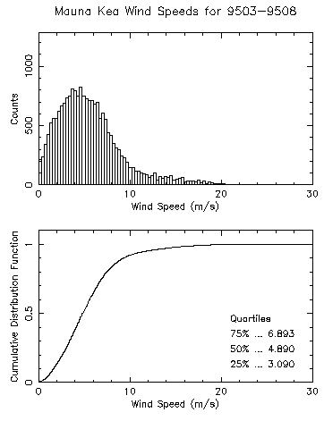
Figure 1. Distribution of wind speeds at the VLBA site on Mauna Kea, Hawaii, for March through August, 1995.These antennas must facilitate observations of polarized radiation. Also, the aperture should have minimal blockage to maximize sensitivity and minimize spurious sidelobes. The optics design should support a 3x3 focal plane array at 230GHz. Mosaicking observations may require uniform aperture illumination, which can be implemented by moving a corrective lens in front of the feed.
The leading candidates for the MMA site are the shield area of the Mauna Kea volcano in Hawaii, that is, a gently sloping area to the northeast of the summit at an altitude of about 3,800m (12,500ft), and a flat region at 5,040m (16,500ft) on the Altiplano (high plateau) of the Andes mountain range 300km east of Antofagasta, Chile, and 50km east of the village of San Pedro de Atacama, Chile. The name of the Chilean site is Llano de Chajnantor. Both locations offer superb atmospheric transparency at millimeter wavelengths. At this writing, the Chilean site appears to have better atmospheric opacity, consistent with its greater altitude.
Figures 1 and 2 show the wind speeds for the Mauna Kea and Chilean sites, respectively, The median wind speed for Mauna Kea is approximately 5 m/s (11mi/h) and for the Chilean site, approximately 7 m/s (16 mi/h). Being exposed, both sites experience high winds associated with storms,
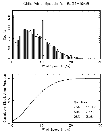
Figure 2. Distribution of wind speeds at Llano de Chajnantor, Chile, for April through August, 1995.although the lower air densities of high elevation mean correspondingly lower air pressures upon the antenna structures. Figure 2 shows the Chilean site to have generally higher winds, as might be expected for a higher altitude site, and the wind speeds to have a broader range than those on Mauna Kea. Figures 3 and 4 show a range of air temperatures for these sites, measured over several months. The thin air provides little insulation against the influx of solar radiation, which will be the significant factor in the thermal response of the antenna structures.
Perhaps most important for reliable operation of the MMA are the physiological effects of the thin air upon service personnel. Ideally, the antenna design should be as simple and robust as possible to minimize service requirements over the 30-year expected lifetime of the antennas. Also, initially as well as from time to time, it will be necessary to re-adjust the antenna surfaces at the site. The antenna design should make these re-adjustments easy to perform .
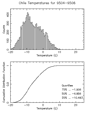
Figure 3. Distribution of air temperatures at Llano de Chajnantor, Chile, April through August 1995.
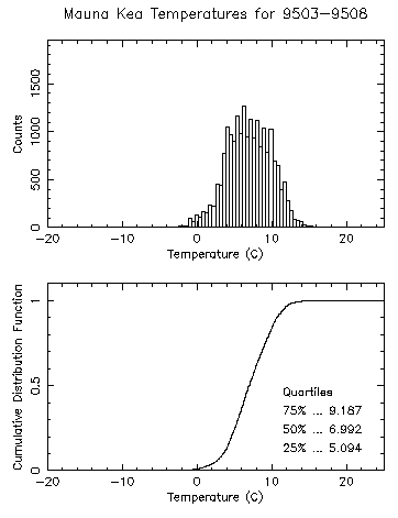
Figure 4. Distribution of air temperatures at the VLBA site on Mauna Kea, Hawaii, March through August, 1995. The MMA antenna group has considered two designs, and Table 2 lists their principal structural elements. One is the conventional symmetric reflector on an "alt-azimuth" mount as shown in Fig. 5(a). The elevation and azimuth axes are orthogonal to one another. This design is based upon the proven 6m antennas used by the Berkeley-Illinois-Maryland Array (BIMA) in Hat Creek, California. Throughout this report we will refer to this design as the "conventional" design. The other design, shown in Fig. 5(b), is an offset reflector on a "slant axis" mount in which the "elevation" axis is not orthogonal to the azimuth axis, that is, slewing the upper support section alone changes the antenna position in both elevation and azimuth. In this report we will refer to this design as the "offset/slant-axis" design.
Both designs use cast aluminum panels whose surfaces have been cut with a numerically-controlled mill for the surface of the primary reflector. Both designs use steel for the pedestals. Both designs use carbon fiber re-enforced plastic (CFRP) for the support structures of the subreflector.
Unlike the conventional design, the offset/slant-axis design uses CFRP tubes instead of steel tubes for the back structure of the surface. It appears that CFRP is necessary for the offset/slant-axis design to meet the thermal performance specifications, whereas the conventional design is marginally able to meet the thermal requirements with steel tubes. At this writing, time prevents evaluation of both designs with identical materials. Where the material cause a significant difference in the performance or cost of the two designs, we have highlighted this difference so that the reader may can judge its impact.
A salient feature of the conventional design is its low aperture blockage. The subreflector support legs are as thin as possible and extend to the edge of the primary reflector. This configuration eliminates the significant triangular shadowing that exists in configurations where the support legs pierce the primary reflector inside its edge, i.e., when the feed legs block part of the spherical wavefront reflecting from the area of the primary reflector outside the feed legs on its way to the subreflector. This design, together with its clean, circularly symmetric, optical path provides good electromagnetic performance. Because similar designs have often been used for radio telescopes, we can be confident of the performance of the conventional design for the MMA antennas.
This conventional design has some disadvantages relative to the offset/slant-axis alternative. One is its higher mass, which requires a stronger transporter and a better road system for reconfiguring the array. Also, the width of the yoke structure constrains the size of the receiver cabin, which must pass between the yoke arms. Most inportant, the yoke structure supporting the backstructure is inherently less stable than the rigid box structure of the offset/slant-axis design.
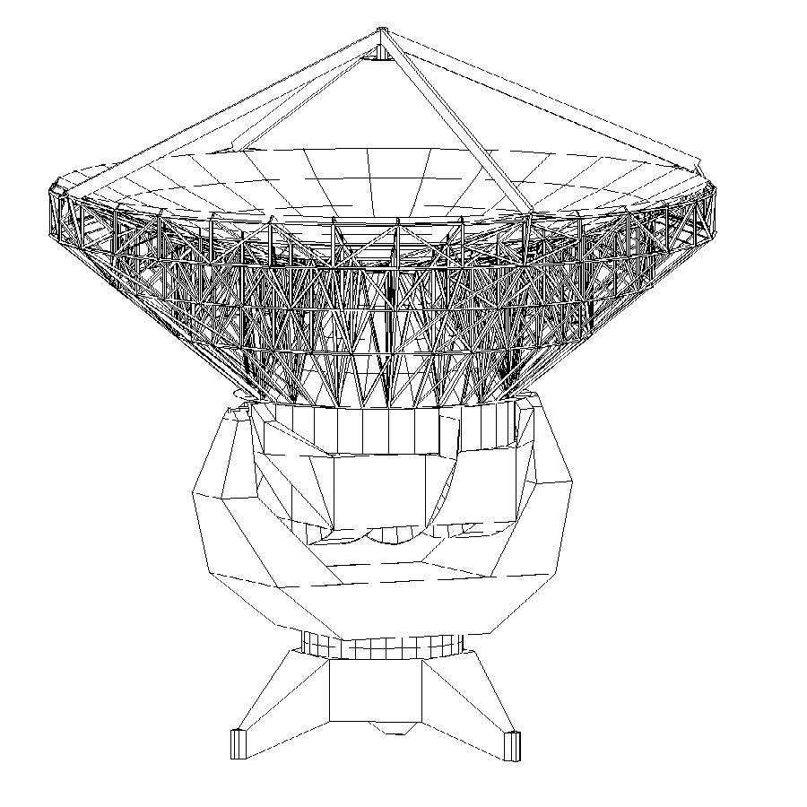
Figure 5a. Two candidate antenna designs for the MMA: (a) the conventional design.
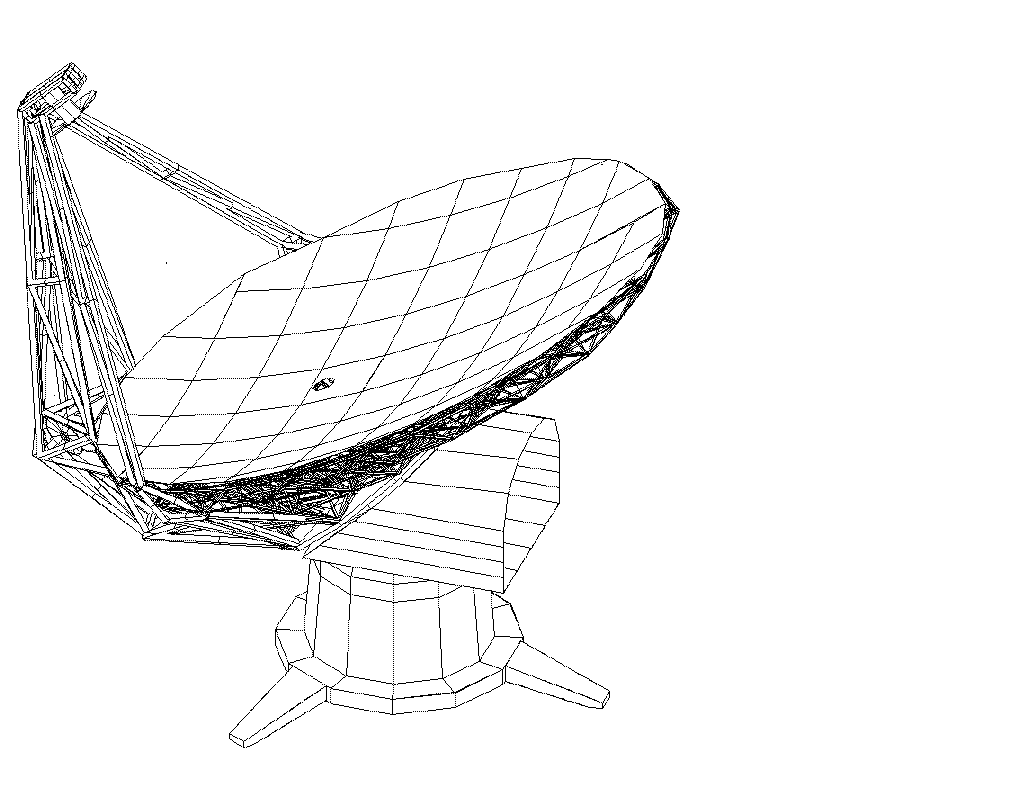
Figure 5b. Two candidate antenna designs for the MMA: (b) the offset/slant-axis design.
In this design the primary reflector is an offset parabola, and the subreflector is supported by a braced monopod at the edge of the primary surface, as shown in Fig. 5b. The feeds and receivers are located in a cabin behind the center of the primary reflector. Because the subreflector and its support lie outside the aperture, the only blockage is a small hole in the middle of the primary reflector to allow the focussed beam to enter the receiver cabin. An optional optics design, which improves polarization and field-of-view performance (see section 5 below), uses two additional flat plate reflectors to bring the focussed beam down the monopod and into the receiver cabin along a path which lies behind the primary reflector, thereby eliminating the small hole in the primary reflector.
The salient features of the offset/slant-axis design are a lower aperture blockage and a lower overall mass than the conventional design. In part, the lower mass results from the absence of a counterweight. A primary structural advantage of the slant axis mount is the absence of a yoke structure, leading to a stiffer mount. The amount of space available for mounting receivers, and access to this space, is less constrained than it is in the conventional design.
A disadvantage of this design is that the asymmetry of the offset reflector degrades the polarization and field-of-view of the antenna. Furthermore, the off-axis monopod support for the secondary mirror is a cantilever structure which increases wind-induced pointing and phase errors. The bearing for the slant axis has to be large and, because the area in the middle ofthe bearing is occupied by the receiver, an on-axis encoder cannot be used. A high precision off-axis encoder is very difficult to design and, hence, may contribute additional pointing errors. Because the offset/slant-axis antenna design is so different from anything previously used for radio astronomy, there is a greater risk of performance problems than for the conventional design.
|
Table 2: Antenna Structural Elements | ||
|
Element |
Conventional |
Offset/slant-axis |
|
Pedestal |
Steel, 10 tonnes |
Steel, 8 tonnes |
|
Reflector mount |
Steel (yoke), 13 tonnes |
Steel (slant cabin), 8 tonnes |
|
Backstructure |
Steel, rectangular tubes |
CFRP tubes |
|
Primary reflector panels |
Machined cast aluminum 120 triangular panels on 5 rings |
Machined cast aluminum 70 rectangular panels |
|
Feed support |
High modulus CFRP tubes |
CFRP box structure |
|
Secondary reflector |
Machined cast aluminum |
Machined cast aluminum |
|
Drive system Wind torque about azimuth axis Wind torque about second axis Moment about azimuth axis Moment about second axis |
Friction 16x (wind pressure in Nm) 48x (wind pressure in Nm) 76 tonne-m2 58 tonne-m2 |
Friction 92x (wind pressure in Nm) 12x (wind pressure in Nm) 84 tonne-m2 47 tonne-m2 |
|
Thermal control |
Sunshield & fans for dish Sunshield for dish ring Sunshield for yoke and pedestal |
CFRP for dish and feed support Sunshield for cabin and pedestal |
|
Encoder |
Elevation - Inductosyn on axes Azimuth - Inductosyn on axis |
Elevation - Off axis encoder (type unknown) Azimuth - Inductosyn on axis |
|
Gravity loading on receivers |
Varies with elevation angle |
Rotates axially with cabin |
|
Lowest natural frequency of structure |
8 Hz |
12 Hz |
Napier (1995) compares the electromagnetic performance of the two designs and Table 3 gives a summary of this comparison. The interpretation of the table entries is as follows:
Rows 1 through 4 of Table 3 lists the relative sensitivity for the designs as a function of frequency. Column 2 gives a figure of merit that is a number proportional to the ratio (On Axis Gain)/(Total System Temperature) known as "G/T". This figure is normalized to the conventional design, whose entry is therefore set to 1.0. Row 1 indicates that at 86 GHz the offset/slant-axis design is 14% more sensitive than the conventional design. Rows 3 and 4 indicate the loss of sensitivity that occurs if 2 additional reflectors are added to the optical path of the offset/slant-axis design to improve its polarization andfield-of-view performance. To obtain these relative sensitivity results, one assumes very low values for atmospheric opacity (ç=0.025 nepers at 230 GHz) and for receiver temperature (Trx =2hf/k where h is Plank's constant, f is frequency and k is Boltzman's constant). Higher values of opacity and receiver temperature would reduce the sensitivity difference between the two antenna designs.
Row 5 shows the degradation in polarization performance caused by the asymmetry of the offset design. This degradation can be eliminated by adding two additional reflectors to reroute the optical path outside the monopod support and under the primary reflector.
Field-of-view is a measure of how rapidly the beam deteriorates when the feed is moved in the focal plane away from the optical axis. The MMA needs a field-of-view sufficient to accommodate future focal plane array feeds, to allow off-axis feeds, if desired, in place of an on-axis rotating mirror for receiver selection, and to accommodate a nutating subreflector for total power stabilization.
Row 6 shows the degradation in field-of-view caused by the asymmetry of the offset/slant-axis design. The number given is the reduction in peak gain that results when the feed is translated in the focal plane by a distance which causes 4.2 beamwidths (BW) of beam scan. This amount of translation is appropriate for the corner elements of a 3x3 focal plane array in which the feed elements are separated by 3 BW.
For either of the proposed mount designs, the antenna beam rotates on the sky as a radio source is tracked. If the beam and sidelobes are not sufficiently circularly symmetric, software corrections will be required to correct for the effect of beam rotation. The conventional design will have a small amount of sidelobe asymmetry due to the unsymmetric quadrupod blockage. Row 7 shows, for an aperture illumination taper of Ä10 dB, the difference in the level of the first sidelobe in the plane of the feed legs and in the 45 deg plane between the feed legs. The aperture illumination for the offset/slant-axis design will be slightly asymmetric, but the amount of asymmetry has yet to be calculated.
|
Table 3: Electromagnetic Performance | ||
|
Parameter |
Conventional |
Offset/slant-axis |
|
Relative Sensitivity (G/T) at 86 GHz |
1.0 |
1.14 |
|
Relative Sensitivity (G/T) at 230 GHz |
1.0 |
1.08 |
|
Relative Sensitivity (G/T) at 86 GHz with 2 tertiary reflectors added to correct polarization and FOV |
Not required |
0.91 |
|
Relative Sensitivity (G/T) at 230 GHz with 2 tertiary reflectors added to correct polarization and FOV |
Not required |
0.90 |
|
Polarization Purity |
No degradation due to antenna. Limit imposed by feed and polarizer |
Circular Pol.: 0.14 BW separation between LCP and RCP beams. Linear Pol.: -22 dB cross polarized sidelobes. |
|
Field of View: gain loss for 4.2 BW scan. |
0 dB |
-2.6 dB |
|
Sidelobe asymmetry due to blockage |
1 dB |
0 dB |
The "total surface error" for an antenna describes a hypothetical antenna with an imperfectly reflecting surface, that is, one assumes that all other components of the radiation path are perfect and that their contributions to the total surface error are negligibly small. Thus, total surface error is a figure of merit that one calculates by combining the errors contributed by parts of the actual antenna by the root of the sums of the squared errors (RSS). This arithmetical method weights the larger contributions heavily and has proved to give a reliable error estimate of an actual antenna.
Table 4 lists estimates for the contributions of individual components to the overall surface accuracy seen by incoming radiation to the antennas. John Lugten estimated the errors for the conventional design and Jingquan Cheng, the errors for the offset/slant-axis design.
Row 1 of Table 4 discusses the error contributions due to the reflector backup structure. Gravity induced errors are larger for the conventional design because of the load of the quadrupod structure supported at the edge of the main reflector. Thermally induced deformations have been estimated using temperature gradients actually measured on the existing antennas of the BIMA array. It is likely that these temperature gradients could be reduced by improving the BIMA thermal control system, so these estimates should be regarded as conservative estimates. The steel backstructure of the conventional antenna has a larger coefficient of thermal expansion, correspondingly, larger errors induced by thermal gradients than the CFRP backstructure of the offset/slant-axis design. Thermal deformations of the conventional antenna could be reduced approximately to the same value as the offset/slant-axis if its backup structure were also made of CFRP.
Row 2 of Table 4 estimates the contributions of the surface panels to the total surface error of the antennas. Both the BIMA and the Submillimeter Array (SMA) organizations have found that cast aluminum panels can be machined to an accuracy of < 8 microns RMS. Typically, such panels are cast in the form of a thin surface supported by deep ribs to produce rigidity with minimum weight. This design also produces a large surface area for good coupling of the panel with the thermalenvironment. Each panel is a section of a paraboloid and, therefore, has a curved surface. Isothermal changes in the panel temperature change the panel focal length without changing the RMS surface error of any given panel. However, if each panel of the surface has a different temperature, then each will assume a different curvature or focal length, and the RMS of the entire surface of the antenna will increase. Additional sources of surface errors contributed by the panels are deformations produced by wind pressure and gravity.
The differences in the error contributions of the panels between the conventional and offset/slant-axis designs are due principally to the larger size of the panels used in the latter design.
Row 3 describes errors contributed by the secondary mirror. These are essentially the same for both designs. Manufacturing errors dominate this component.
This row presumes that final adjustment of the antenna surfaces will be made by comparing the phase of an incoming plane wavefront to that reflected from the primary mirror. Knowing the wavelength of the incoming waves, one converts the phase differences from angular to linear units. In radioastronomy this technique is called "holography" because it uses phase as well as amplitude information to make an image of the primary mirror. It has become the standard way to adjust the surfaces of antennas used for millimeter wavelengths. Presently, experience shows it's possible to measure the surface figure and set the surface panels within about 8 microns.
|
Table 4: RMS Surface Errors ( microns ) | |||
|
Error source |
Conventional Design |
Offset/slant-axis Design |
Notes |
|
Backing structure gravity(ideal) gravity(non-ideal) absolute temp temp gradient wind total |
12. 2. 1.5 18. * 1. 21.8 |
8. 4. 2. 10. 3. 13.8 |
*Daytime worst case error. Night time performance is significantly better. With CFRP backup structure, would be same as offset/slant-axis design |
|
Panels manufacture absolute temp temp gradient gravity wind Panel mounting total |
6. 2. 2. 1.5 1. 0.5 6.9 |
9. 4. 4. 6. 6. 1. 14.* |
* Larger rectangular panels are proposed for offset design. Both designs use same type machined cast aluminum panels |
|
Secondary mirror manufacture absolute temp temp gradient gravity wind aging* alignment total |
6. 0.5 1. 1. 0.5 0.5 2. 6.3 |
6. 0.5 1. 1. 0.5 2. 2. 6.8 |
*Secondary mirror larger for offset/slant-axis design
|
|
Holographic setting total |
8. |
8. |
|
|
Grand total (RSS) |
25. |
22. |
|
The pointing errors for any antenna fall into two classes: repeatable and nonrepeatable. Repeatable errors are those associated with physical effects that remain unchanged for long periods such as weeks or months or years. This category includes gravitational deformations, bearing irregularities, and foundation settling. Calibration at appropriate intervals can compensate for these errors. Repeatable errors are thus easily accommodated and are not considered further here.
Nonrepeatable errors in a well-behaved structure stem from two main causes: temperature and wind. Errors from both sources can be reduced (but seldom eliminated) by instrumentation such as multiple temperature sensors, electronic levels, and lateral displacement sensors. The difficulty of installing, implementing and maintaining such instrumentation on the forty MMA antennas has persuaded us to avoid designs requiring such complex corrections. Nonetheless, provision must be made for the installation of such instrumentation so that it can be used to improve performance if required.
A major problem in analyzing pointing changes resulting from thermal effects is to define accurately the temperature distribution over the antenna structure. For this purpose we have made extensive use of a series of temperature measurements made on a BIMA antenna by Lamb and Forster (1993). Row 1 of Table 5 summarizes the thermal pointing errors for both the conventional and offset/slant-axis antenna designs. The temperature differences and rates of change of temperature are estimates based on the BIMA 6m measurements. These are typical summer daytime values at Hat Creek and each corresponds to an RMS temperature deviation across the antenna surface of 0.6C and a feedleg temperature difference of 1.5C. With the expected rate of change of thermal pointing error for the conventional antenna, an astronomical pointing calibration every 30 minutes will be sufficient to keep pointing errors below one arc second.
Row 2 of Table 5 summarizes the wind induced pointing errors. In contrast to the thermal effects, the wind-induced pointing errors are straightforward to calculate. The total wind induced error is the RSS of the component values and the errors vary as the square of the wind velocity.
|
Table 5: Estimated Pointing Errors | |||
|
Item |
Conventional Design |
Offset/slant-axis Design |
Notes |
|
Daytime Thermal Pointing Errors | |||
|
Dish RMS Error Feedleg RMS Error Yoke RMS Error Total RSS Error Rate of Change of error |
1.2 arcsec* 0.2 arcsec 0.9 arcsec** 1.5 arc sec 1.3 arcsec/hr |
0.2 arcsec negligible 0.2 arcsec negligible |
* The conventional antenna with a CFRP backing structure will perform as well as the offset/slant-axis antenna. **A tilt meter, thermal insulation, and active temperature control will reduce these values |
|
Typical Wind Pointing Errors | |||
|
Secondary Mirror* Yoke Structure* Other* Total Wind RSS Error |
0.6 arcsec 0.9 arcsec 0.5 arcsec 1.2 arcsec |
1.0 arcsec 0. 0.1 arcsec 1.0 arcsec |
* Assumed 9m/s (20 mi/h) for wind speed |
|
Scaled RSS Wind Pointing Errors* | |||
|
12 m/s (27 mi/h) 6 m/s (13 mi/h) 3 m/s (7 mi/h) |
2.1 arcsec 0.6 arcsec 0.2 arcsec |
1.8 arcsec 0.5 arcsec 0.1 arcsec |
* Wind-induced errors should scale as v2 |
|
Total Wind and Thermal Pointing Errors, RSS | |||
|
12 m/s (27 mi/h) |
2.6 arcsec |
1.8 arcsec | |
"Phase errors" is a term used to describe the errors in the detected phase of incoming wavefronts, that is, phase errors induced by the antenna system through variations in the wave pathlength. In an interferometer such errors degradesensitivity and image quality. As with pointing errors, phase errors fall into two classes: repeatable and non-repeatable. Repeatable errors result from structural variations from one antenna to another, from variations in cable or waveguide sections, etc. Such errors are long-term, can be easily compensated through calibration, and will not be further discussed here. In contrast, non-repeatable pathlength changes are primarily caused by thermal and wind deformations of the antenna and, as such, can vary on short time scales.
Table 6 lists the sizes of these pathlength errors for the two antenna designs. Data row 1 details the thermal phase errors. Again, as with pointing, the difficulty with the thermal analysis is to know what temperature distribution and rate of change of temperature to assume for the antenna structure. We use the same BIMA measurements described in section 7 above typically observed in about a 30 minute time period. Within this time interval the temperature changes for the mount and reflector backup structure are 1C and 1.5C during the day and 0.3C and 0.5C at night. The size of the RMS pathlength errors resulting from these temperature changes is shown in Table 6 as "phase error". In the column "after calibration" is the residual path length error if phase is calibrated astronomically every 3 minutes. The residual phase errors increase proportionately for calibration intervals longer than 3 minutes.
Data row 2 of Table 6 gives the RMS pathlength errors due to wind deformation of the antenna. The calculation assumes that wind phase errors will vary sufficiently rapidly so that they cannot be corrected with phase calibration on a 3minute time scale.
Data row 3 provides a phase error budget for miscellaneous items such as bearings, panel adjusters, receiver position and other structural deformation.
|
Table 6: Phase Errors | ||||
|
Item |
Conventional Design |
Offset/slant-axis Design | ||
|
Phase Error |
After calibration every 3 min |
Phase Error |
After calibration every 3 min | |
|
Thermally-induced errors (peak value) | ||||
|
Thermal gradient (daytime) Thermal gradient (nighttime) |
140 microns * 45 microns * |
14 microns 5 microns |
50 microns 30 microns |
5 microns 3 microns |
|
Wind-induced errors (peak value) | ||||
|
12 m/s (27 mi/h) wind 9 m/s (20 mi/h) wind 6 m/s (13 mi/h) wind 3 m/s (7 mi/h) wind |
26.7 microns 15 microns 6.7 microns 1.7 microns |
26.7 microns 15 microns 6.7 microns 1.7 microns |
17.8 microns 10 microns 4.5 microns 1.1 microns |
17.8 microns 10 microns 4.5 microns 1.1 microns |
|
Other errors (peak value) | ||||
|
Miscellaneous sources |
10 microns |
10 microns |
10 microns |
10 microns |
|
Total RMS errors | ||||
|
Best condition Average condition Worst condition |
5 microns 7 microns 10 microns |
2 microns 4 microns 6 microns | ||
* These large values result from using different materials for the quadrupod (CFRP) and reflector backup structure (steel). Using CFRP for the back structure will reduce the errors of the conventional antenna to approximately the same values as the offset/slant-axis design.
Phase errors caused by the atmosphere can quickly vary. To compensate for these errors, it is theoretically possible to move all the antennas rapidly to a nearby calibration source and then back to the astronomical source. This "fast-switching" calibration cycle would need to occur within six seconds to be effective. This calibration scheme requires antennas that can slew and settle extremely rapidly. Such slew rates can excite structural resonances, in particular those involving lateral movements of the subreflector. Woody (1995) has shown that
slewing using carefully profiled trajectories can minimize the excitation of these resonances. The trajectories must be very smooth, probably requiring friction drives without gears.
Table 7 lists the antenna performance we might expect. The pointing errors listed are the RMS pointing errors remaining after initiating the fast switching cycle. We assume the amount of damping to be the natural damping provided by the construction materials. Even with the improved switching profile, the residual pointing errors are several times larger than needed. We expect that further work on a fully optimized switching profile can reduce the errors to meet specifications. However, the risk remains that our simplified computer models do not predict the actual dynamic performance adequately. If further improvement is needed, it may be possible to use active or passive damping on troublesome parts of the structure.
Our preliminary calculations as well as discussions with manufacturers of damping technology suggest that such damping techniques will work. These techniques are new and untried in antenna technology. They will require a development program which, like all such programs, may not be successful. Therefore, we believe it essential to construct and test a prototype antenna before commencing full production of the 40 MMA antennas.
|
Table 7: Fast-Switching Performance | ||
|
Time |
Conventional (8 Hz resonance) Error after 1.5 degrees; step |
Offset/slant-axis (12 Hz resonance) Error after 1.5 degrees; step |
|
Normal Slew Trajectory | ||
|
After 1 second time After 2 seconds time |
50 arcsec 15 arcsec |
35 arcsec 10 arcsec |
|
Improved Slew Trajectory | ||
|
After 1 second time After 2 seconds time |
12.5 arcsec 5.0 arcsec |
8 arcsec 3.5 arcsec |
Images of spatially extended objects require observations with the shortest possible interferometer baselines (Welch, 1995), a configuration known as "close packing" of the antennas. Specifically, close-packed configurations enable measurements of spectral components at small u-v coordinates, which contain significant information for spatially extended objects.
Table 8 lists the closest possible separations for the MMA array using the two antenna types. Row 1 gives the smallest separation between antenna centers for random orientations of the antennas. This case is the most conservative because it allows for inoperative antennas. Row 2 gives the smallest separation that can be allowed if all antennas are pointed in the same direction. This case is the most optimistic. It requires reliable anti-collision sensing equipment and shutdown switches on the array because, if antennas do not point in the same direction for any reason, they can collide.
When two antennas are close together, one antenna can block radiation from the one behind it when observing sources at low elevation. This condition, known as "shadowing", is a design consideration for multi-element interferometers. It appears that, for the MMA configurations, there is no significant difference between the two antenna designs with respect to the amount of shadowing providing the antennas are pointing in the same direction.
|
Table 8: Close-Packing Performance | ||
|
Case |
Conventional Design |
Offset/slant-axis Design |
|
Safe minimum packing distance between antennas. No protection required. |
1.53×diameter = 12.2 m |
1.36×diameter =10.9 m |
|
Minimum packing distance between antennas pointing in same direction. Collision protection required. |
1.13×diameter = 9.04 m |
1.20×diameter = 9.60 m |
Table 6 compares the estimated cost of the two antenna designs. These estimates result from experience building antennas for the BIMA interferometer at Hat Creek, California, and the Submillimeter Array now being constructed on Mauna Kea, Hawaii. While we believe the accuracy of these estimates to be in the 10-20% range, additional studies will be necessary to confirm these costs.
|
Table 9: Estimated Cost of the Antenna Designs in 1994$ | ||
|
Element |
Conventional Design |
Offset/slant-axis Design |
|
Simple steel structure ($1/pound) |
$110,000 |
$60,000 |
|
Bearings |
35,500 |
70,000 |
|
Panels |
150,000 |
170,000 |
|
Drive system |
100,000 |
100,000 |
|
Surface back structure Dish Sub-reflector support Panel adjusters Subtotal |
100,000* 80,000 40,000 220,000 |
230,000 150,000 30,000 410,000 |
|
Encoder |
70,000 |
100,000 |
|
Thermal control |
25,000 |
15,000 |
|
Sub-reflector mirror |
30,000 |
40,000 |
|
Pointing instruments |
60,000 |
60,000 |
|
Transportation and assembly |
400,000 |
400,000 |
|
Other |
100,000 |
100,000 |
|
Grand total |
$1,300,000 |
$1,525,000 |
*Increase by approximately $150,000 for CFRP instead of steel structure
We divide the conclusions drawn from this initial work on the antenna design into three broad categories:
i. The conventional antenna design with CFRP feed support and steel backing structure gives excellent electromagnetic performance. This design meets the current specifications regarding pointing accuracy, surface accuracy and phase stability if phase calibration is performed every few minutes and pointing calibration, every 30 minutes. The mix of structural materials leads to a strong dependance of phase errors upon temperature. Using CFRP instead of steel for the surface back structure would greatly reduce these errors. The yoke structure is inherently less stable than the corresponding box structure of the offset/slant-axis design, but the instabilities appear to be manageable—especially if insulation and thermal control are used.
ii. The offset/slant-axis design also meets all current specifications. Although the simple asymmetric optics lead to poor polarization and field-of-view performance, the addition of two reflectors to the optical path can overcome these problems but at the cost of reduced G/T performance. These reflectors would reroute the optical path from the subreflector around the edge and under the primary surface rather than through a hole in the primary. The concomitant reduced G/T performance is significant only when the antennas are used at the very best site with the very best receivers, that is, at the extreme limit of the array capability.
iii. Each design falls slightly short of the fast switching and settling requirement. Additional work is needed to develop and refine the switching algorithms and to determine the feasibility and cost of active or passive damping to reduce the structural settling time.
i. Are the frequent phase and pointing calibrations required by the conventional antenna with a steel backstructure acceptable? This calibration procedure may not be adequate if the MMA performance is extended into sub-mm bands. Would the increased cost (approximately $150k per antenna, or $6M for 40 antennas) of a CFRP backstructure be justified by the improved performance of the conventional antenna?
ii. Are the relatively poor polarization and off-axis performance of the offset/slant-axis design serious problems? Although additional mirrors can overcome these specific problems, is the accompanying degradation in G/T acceptable?
iii. Is the wind speed adopted for the pointing specification reasonable? This leads to an RMS pointing error of 1 arcsec 50% of the time.
iv. Is subreflector nutation necessary? While subreflector nutation is possible with either antenna design, it increases costs by approximately $800K for 40 antennas and increases complexity. If necessary, is nutation only in the azimuth direction adequate?
i. Based upon the analysis available now, the AWG would choose the conventional design for the MMA antennas although either design would be acceptable, each with different shortcomings. For both designs, more design work is required to meet the stringent specifications for fast switching and settling. Additionally, the AWG believes it would be prudent to investigate a combination of the two designs discussed here: a conventional reflector with a CFRP back structure on a slant-axis mount. If frequent calibration for phase and pointing errors is not possible, then the combination structure would be a better design.
ii. The AWG believes that the stringent performance specifications (particularly the fast switching) make it prudent to build and test a prototype antenna before committing funds for the remaining 40 antennas.
References
Lamb, J. and Forster, R, "Temperature Measurements on BIMA 6-m Antennas—Part I: Backing Structure", MMA Memo No 100, 1993.
Napier, P. J., "Electromagnetic Performance Comparison of an Offset and a Conventional MMA Antenna Design",MMA Memo No 135, Sept., 1995.
Welch, W. J.,"Some Comments on Sampling , Antenna Spacings, and Uniform Aperture Illumination", MMA Memo No 134, 1995.
Woody, D. P., "Optimized Trajectory for Fast Position Switching", in preparation, 1995.
This document was produced using an evaluation version of