1. Summary
Antennas in the diameter range 8 m to 15 m with a surface accuracy
specification of 25 µm and a pointing requirement of 1/30 th beamwidth
at a frequency of 300 GHz have been studied to determine feasibility and
cost. Antennas with this desired performance are feasible over the full
diameter range, although the margin with which the requirements can be
met reduces as the diameter increases. For general project definition purposes
an antenna production cost of $24K/sq.m of antenna collecting area can
be assumed, to which an additional one-time cost of approximately $11M
must be added. This production cost implies a cost scaling in which antenna
cost increases as the square of the diameter, which is a slower rate of
cost increase than is usually assumed. The relatively low cost of the largest
diameter antennas is achieved with a number of design innovations,
in particular the use of a commercial active laser metrology system which
corrects for pointing errors caused by the antenna foundation and mount
and allows the cost of these elements to be reduced. Such a metrology system
is not yet in use on any existing telescope and needs further development.
2. Introduction
The LSA/MMA antenna study committee was formed to provide information about the cost and performance of millimeter wavelength antennas. This information is required to help define a new array to be built by the possible merging of the European LSA Project and the US MMA Project. The committee met initially in Grenoble on 19-21 August, 1997 (Napier, 1997). At this meeting it was decided that, in order to cover the range of antenna diameters of potential interest, the NRAO would study antenna designs for 8 m and 10 m diameter, ESO would study a 12 m design and IRAM would study designs for 12.8 m and 15 m diameter. The committee met for a second time in Socorro on 30 Sept.-2 Oct., 1997. This report includes the material presented and discussed at that meeting and completed since the meeting.
3. Design and Performance Information
In this section we provide information about each of the designs studied and its predicted performance. The performance numbers are collected together in Table 1 and are discussed in more detail in the individual sections.
The principal design goals used to generate the antenna designs are as follows:
(1) Pointing Accuracy. 1/30th beamwidth rms at 300 GHz. This requirement to be met in the median wind for the 5000 m site (6 m/s) and with astronomical calibration for thermal effects allowed every 30 min during the day. Beamwidth is assumed to be 1.2*wavelength/diameter.
The pointing entry in Table 1 is the pointing error resulting from a static wind load. If the wind is sufficiently constant in time, this number could be reduced by reference pointing on a nearby astronomical source by as much as a factor of 0.25 to 0.5 (Holdaway et.al., 1996). In Table 1 two pointing numbers are given, one for the basic passive structure and another, improved, number for pointing with an active metrology system turned on. For the 15 m design the active metrology system is essential to the operation of the telescope drive system and so no number for passive pointing is given. Recently, the problem of pointing errors caused by "anomalous refraction" in the atmosphere has been investigated (Holdaway, 1997; Lucas, 1997). For comparison, to indicate the relative size of antenna and anomalous refraction pointing errors, Holdaway’s (1997) estimate for median pointing error due to anomalous refraction at 50 degrees elevation is included in Table 1. These values require further checks, however.
(2) Surface Accuracy. 25 µm rms in median wind and all normal daytime and nighttime thermal conditions. The number in Table 1 is for the elevation range 25 to 75 degrees.
(3) Pointing Fast Switching. 1.5 degrees in 1.5 seconds (time from beginning of move to start of data taking). This requires that the lowest resonant frequency of the antenna be greater than about 6 Hz and the predicted value for this frequency is included in Table 1.
(4) Phase Stability. 10 µm rms in median wind. Calibration allowed every few minutes during day for thermal effects. The number given in Table 1 is for a static wind load of 6 m/s.
(5) Close Packing. Minimum baseline < 1.3 x (Antenna Diameter).
(6) Transportability. Road mounted transporter for terrain of high site.
(7) Direct observations of the Sun allowed. It is expected that the only consequence of this requirement for the antenna will be the need to roughen the surface of the reflector panels by a few microns to diffuse the reflection of solar energy.
(8) Low Antenna Noise. Cassegrain focus, no tertiary reflectors, minimum blockage feedlegs. The blockage number given in Table 1 is total blockage including both subreflector and support legs. Note that different designers made different assumptions about thermal and gravity loading on the feedlegs and this makes a meaningful comparison of blockage between the different designs difficult. Thus, the 8m blockage is for a feedleg width of 6 cm whilst the 12m blockage assumes a width of 3 cm. Also, antenna noise caused by ground reflections from the feedlegs is as much a function of the angle between the feedleg and the reflector axis as it is a function of the blocked area. In general, the larger this angle, the less the antenna noise, but this effect is not quantified in Table 1. The question of the optimum size, location, number and shape of the feedlegs needs a careful study before an antenna design is completed.
(9) Single Dish (total power) Observing Mode. Possibility for subreflector nutator to be included.
It should be noted that there was not complete agreement within the group concerning the feasibility of achieving requirements 8, 9 above. More work is needed to understand the need for, and difficulty of satisfying, these requirements.
Table 1. Summary of antenna performance data.
| 8 m | 10 m | 12 m | 12.8 m | 15 m | |
| Pointing requirement, 1/30 th beamwidth at 300 GHz (arc.sec). | 1.0 | 0.83 | 0.69 | 0.64 | 0.55 |
| Wind pointing without active metrology (arc.sec) | 0.5 | 0.7 | 0.4 | NA | NA |
| Wind pointing with active metrology (arc.sec) | 0.3 | 0.3 | 0.3 | 0.4 | |
| Median anomalous refraction pointing error, 50 degrees elevation (arc sec) | 0.6 | 0.6 | 0.6 | 0.5 | 0.5 |
| Surface accuracy (µm) | 16 | 20 | 25 | 20 | 25 |
| Wind phase error (µm) | 8 | 16 | <10 | 10 | |
| Resonant frequency (Hz.) | 9 | 9 | 8.5 | 12 | >10 |
| Blockage (%) | 3.0 | 2.5 | 3.1 | <2.4 | 2.4 |
3.1. 8 m Diameter

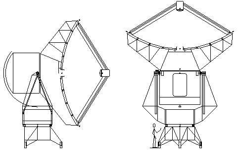
Figure 1. NRAO 8m antenna design.
The 8 meter antenna design uses a symmetrical reflector, a Cassegrain optical configuration, and a conventional elevation-over-azimuth mount and has several improvements compared to the design described in an earlier report (Napier et. al., 1995). The subreflector is light weight machined aluminum and the panels of the main dish are machined aluminum castings. The dish backup structure is currently slated to be entirely CFRP (no metal nodes except for attachment of external structures), however a steel backup structure is probably acceptable at a substantial cost savings. The receivers are located at the Cassegrain focus, which has an effective focal ratio of approximately f/6.2, in a large (approximately 3m by 3m by 2.5m) temperature controlled cabin, which also houses much of the antenna electronics. The mount is constructed from welded steel plate. Elevation bearings are a pair of spherical roller bearings; the azimuth bearing is a single 2 m diameter bearing, probably the cross roller type. All bearings are sealed. The antenna base sits on the foundation at 3 points, giving a quasi- kinematic support (radially compliant feet accommodate differential thermal expansion between the steel base and the concrete foundation); each antenna and each base are pre-leveled, which allows rapid reconfiguration of the array. Choosing instead a base supported at 4 or more points may increase the antenna stiffness, but may increase the time required for array reconfiguration.
The overall geometry of the antenna is shown in Figure 1. The antenna geometry allows antenna center-to-center spacings as small as 1.27 dish diameters with no possibility of collision for elevations above 22 degrees. The diameter of the main reflector can be increased to 10 or 11 m without requiring changes to the mount geometry; the number of panels can be kept constant at 120, even for a 10 or 11 m dish diameter (the largest panel dimensions are then about 1 m). This design has some special features which are key to its excellent performance, but carry some modest risk. First, each antenna base is outfitted with a pair of tilt meters which will measure the tilt of the azimuth bearing due to deformation of the foundation and antenna base. Also, each arm of the yoke contains a CFRP A-frame structure and sensors to measure yoke deflection, which allows correction of pointing errors about the elevation and azimuth axes, and phase errors. Finally, the mount will be shaded from direct solar heating (if a steel backing structure is used, air circulation fans and sunshades are necessary). Each of these points is discussed further in the Special Features section below.
Performance Summary
The pointing performance is calculated for a 6 m/s wind velocity, for the standard air density at 5000 m elevation, using the force coefficients of Levy (1996). For the dish pointing directly into the wind, the pointing error is 0.2 arcsec with the tilt meters inactive, but reduces to 0.06 arcsec with the tiltmeters activated. The pointing error is estimated to be better than 0.5 arcsec over the whole sky.
The phase change due to wind deflection of the mount is less than 4.1 microns worst case.
The surface RMS is less than 16 microns over the whole sky; the gravitational deformation of the backing structure is about 11 microns and the thermal performance of the CFRP backing structure is excellent since metal nodes are avoided.
The blockage due to the subreflector is 0.79% and the blockage due to
the quadrupod is 2.21%. Because the legs extend to just inside the dish
edge, all of the quadrupod blockage is blockage
of the plane wave.
Special features
Each antenna base is outfitted with a pair of tilt meters located on the non-rotating structure at the height of the azimuth bearing. These tilt meters will measure the tilt of the azimuth bearing due to deformation of the foundation and antenna base. Also, each arm of the yoke contains a CFRP A-frame structure which carries no load, but provides a stable reference for the elevation encoder, and allows measurement of yoke deflection. This CFRP reference structure automatically corrects most of the elevation pointing error which results from bending of the yoke due to either wind loading or thermal gradients. In addition, 4 displacement transducers (e.g. Schaevitz 050HR or similar) measure the lateral and vertical translation of each of the yoke arms; this completely determines the azimuth pointing error (tilt of the elevation axis and wind-up of the yoke arms) and the instrumental phase change due to deflection of the yoke arms. Thus, with the tilt meters to correct for the base and foundation tilts and the reference arms to correct for most of the yoke deflection, mount contributions to pointing error and instrumental phase are almost completely removed.
Two other notable features are that the panels of the main reflector
are supported at 4 convenient points, but in a way that they cannot apply
significant loads to the backing structure due to their own stiffness or
thermal excursions. The antenna's elevation range is 0 degrees to 120 degrees;
holographic surface measurement over this very large range is very important
for setting the surface
to minimize the maximum RMS over the typical observing range, say 15
to 75 degrees.
3.2. 10 m Diameter
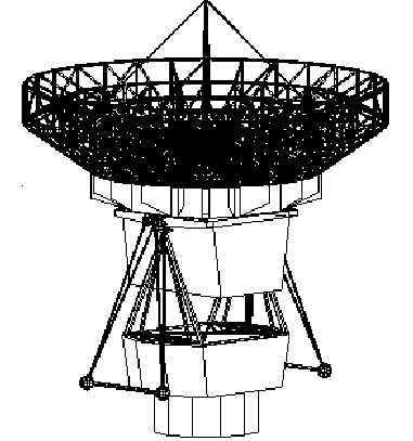
Figure 2. NRAO 10 m antenna design
The present 10-m antenna design is shown in Figure 2 (note: in the figure the dish depth is not to scale, the dish should be thinner). The design has the following features:
1) Cast aluminum panels with dimensions of about 1 m are used. The panels should be thin and be supported at the four corners. The expected weight of the panel is between 15 - 22 kg/ m2. The dish will have 5 rings of panels. The outer four rings will have 32 panels for each ring and the inner one has 16 panels.
2) The dish is a CFRP double-layer truss structure. The dish support ring has a radius of 3.2 m. The support ring has 16 equal softness points. For this deflection driven design, the maximum distance of the dish surface points to a nearby support point is smaller compared with a six-point supported dish.
3) Four feedlegs are supported at the same radius of 3.2 m. However these support points are separate from the 16 dish support points. It is intended that the radius of the feedleg support on the top of the dish is also 3.2 m in radius, which results in small blockage but not as low as could be achieved with the feedlegs supported at the edge of the reflector.
4) A steel sub-ring is provided to produce 16 equal softness points. The steel ring also provides torsional stiffness. The steel ring is supported by 4 points from the elevation beams. The sub-ring also provides 4 feedleg support points.
5) Between two elevation beams, a strong platform is provided to house the receivers and other equipment. Cabin space is provided. The size is 3 m x 3.3 m on the top and 2.4 m x 3.3 m on the bottom, the height is 2 m. A permanent cabin box is not preferred so as to avoid any unexpected loading to the BUS structure, although provision has been made to avoid transferring any unwanted moments to the dish structure.
6) Counterweight is arranged on both sides of the elevation beams. Soft counterweight support is preferred. However, to reduce risk, a stiff counterweight support should be prepared for the first test antenna. In theory, a soft swinging counterweight(~0.2 Hz) will not harm the antenna pointing. Damping by using polymer material is another way to solve the problem.
7) DC torque motor drives are used at both elevation axis.
8) CFRP and invar truss yoke structure is used. The invar bars are used at the bottom of the yoke for taking tension loading. This truss design will have nearly zero thermal pointing problem (for steel yoke of 1 inch wall thickness, the pointing error with 30 minutes could be 0.9 arcsec and for a thinner wall thickness (e.g. 0.5 inches) this error could double.). In the preliminary calculation, the CFRP tube has a medium modulus and the weight of the material is small. If higher modulus or more material is used, the wind pointing error of the yoke could be reduced again.
9) The bottom of the yoke is connected with a strong steel yoke base through some slot-like linear guiders. Since the total movement due to temperature change is about 1 mm, the linear guider is not complex in design. The steel structure also supplies some stiffness for the yoke in the vertical direction. On top of the yoke base, rails may be installed in helping the receiver mounting. The yoke base is thick, it may cover both the top and the bottom of the azimuth bearing. On the front and back sides of the yoke base, holes are provided for antenna lifting.
10) An enclosed azimuth bearing is used. The antenna base is cylindrical in shape. Inside the base is a cable wrap.
11) Tilt meter, laser quadrant detectors, and laser angle detectors could be used in improving the antenna performance in the future.
In summary, the 10-m design is light in weight. It is about 25 tonnes in total weight. This design, which still needs further optimization, will provide very stable pointing, phase and surface accuracy. Frequent calibration of the phase and pointing may be not so important, especially the pointing. On the windy Chile site, the open truss yoke structure and the cabin-free design will have minimum wind drag force over a wide range of sky coverage. This design is low in cost and the light weight design will also reduce the cost of other parts of the system including foundation, transporter, service road, service shelters and the reconfiguration of the array.
3.3. 12 m Diameter
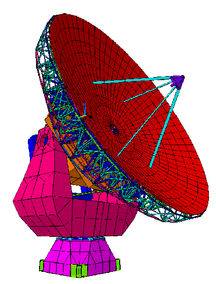
Figure 3. ESO 12m design
The 12 m Submillimeter antenna studied by the European Southern Observatory has a conventional structural design that is highly optimized. Reference is made to the specifications below ( Table 2), to Figures 3 and 4 and to Andersen (1997).
The antenna has a traditional alt-az mount. The dish panels are of lightweight aluminum. The truss structure of the dish is made of CFRP tubes and is prefabricated by epoxying the tubes together in the node points. Fabrication of the truss structure takes place on a full-size jig in the workshop. The base, yoke, center section, counterweight and box structure under the dish are all made of steel.
The azimuth bearing is a large ring bearing, possibly of cross roller type. The elevation bearings are double spherical bearings capable of carrying axial loads in both arms. The motors are of the direct-drive type. There is one for the azimuth movement near the azimuth ring bearing and two for elevation on the inside of each yoke arm. Use of such motors leads to an inexpensive and reliable design with highly optimized servos. The encoders are commercially available directly coupled optical disk encoders with a resolution of about 0.01". Due to the high resolution, the encoders can also be applied as tachometers.
The antennas can be moved by means of a special transporter, which is a heavy trailer pulled by a truck. The trailer has a U-shape so that it can be attached to the antenna on both sides of the base.
It is foreseen that the telescopes are pre-assembled in Europe or the United States and transported to Chile divided into a few subassemblies. The complete truss structures for the dishes are shipped as single units to Chile. Final assembly of the telescopes takes place in San Pedro. After assembly, they are moved to the Chajnantor site using the transporters.
Table 2. Extract of Specifications
| Item | Value | Comments |
| Antenna diameter | 12 m | |
| Main reflector f-ratio | f/0.35 | |
| Exit f-ratio | f/8 | |
| Scale | 0.465 mm/" | |
| Beam width | 19.8" | 10 dB tapering |
| Pointing precision | 0.66" | Max
Offset over 30 minutes |
| Surface errors | 25 µm rms | Max |
| Receiver cabin | 3m*3.75 m | |
| No of panels | 135 | |
| Mass | 50 t |
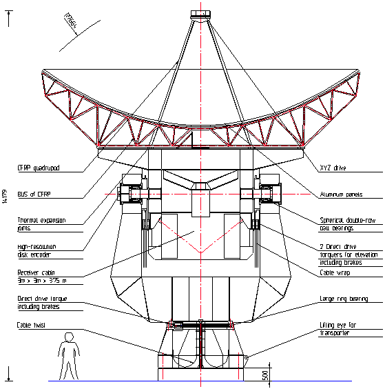
Figure 4. ESO 12m antenna design
Only a tentative foundation design has been carried out. It appears that foundation cost is significant and highly design dependent. Hence it is advisable to carry out a detailed study, including soil investigations, to find a low-cost foundation solution.
Error budgets for surface precision and pointing have been set up and the performance of the antennas has been studied by finite element calculations. It has been shown that the gravity induced error of the main reflector over the typical pointing range is about 3 µm rms. It is a prerequisite that the subreflector is continuously adjusted to its optimal position during observations as in a normal homologous design.
Wind calculations have been carried out for a few representative pointing angles. More detailed wind calculations are still pending. A wind velocity of 6 m/s has been assumed as limit for full performance. Calculations show that the primary reflector deformations induced by wind (<3 µm) are negligible and that the main influence of wind is related to pointing precision. It is required that the antenna points better than 0.66" in offset over 30 minutes. Wind induced pointing errors have been found to be less than 0.4" and are therefore acceptable.
Thermal performance has not yet been studied. However, there is good hope that no major thermal problems will be present since the dish backup structure is made of CFRP without steel nodes. The large steel structures will be thermally insulated to reduce solar heating.
The lowest eigenfrequency of the antenna has been computed to be 8.5 Hz. This value seems entirely satisfactory.
All calculations indicate that the telescope will fulfill specifications for submillimeter operation. However, to provide larger safety margins it seems advisable to develop a laser-based optical system that measures alignment errors for the elevation axis.
It can be concluded that there is good evidence that the 12 m submillimeter telescope can be built as proposed and will fulfill specifications.
3.4. 12.8 m Diameter
The 12.8m IRAM telescope is an exact copy of the proposed 15m telescope (see Section 3.5 below) except that the reflector diameter is reduced by one ring of panels. First computer calculations for gravity loads indicate an important gain in performance (see Figure 5 for comparison). The performance data of the 12.8m telescope (Table 3) can therefore only be indicated tentatively as computer verifications for all load cases are pending :
Table 3. Performance of 12.8 m telescope.
|
surface accuracy |
pointing error |
phase stability |
resonant frequency |
blockage (no taper) |
|
~20 µm r.m.s. |
~0.4 arc sec rss |
< 10 µm r.s.s. |
~12 Hz |
< 2.4% |
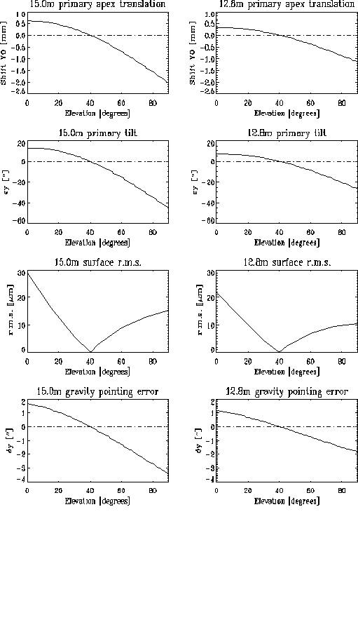
Figure 5. Comparison of Gravity performance of 15.0m and 12.8m antennas.
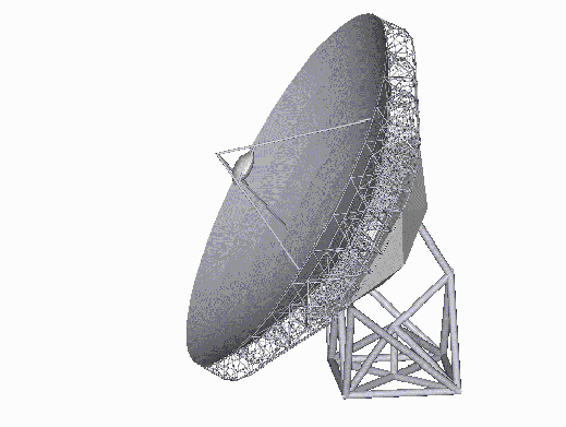
Figure 6. Computer vision of the IRAM 15m telescope
The proposed 15m telescope (Plathner et. al., 1997) is shown in Figure 6 as a simplified computer vision. It is an alt-az mount telescope with the elevation axis off-set to increase stiffness in the reflector support system and to render the pedestal more compact. In addition, it facilitates the installation of an optically linked 2-axes encoder system which permits control of the reflector position independently of wind and temperature-induced deformations in the pedestal by a master-slave servo train.
The particular truss structure of the pedestal transfers the reflector loads directly into the ground via four bogies and a central bearing defining the az. axis position. This increases the lowest resonant frequency to values above 10 Hz and contributes to the high pointing accuracy of the whole telescope.
Fig. 6 indicates schematically the motion of the 15m telescope in elevation which is achieved by a linear drive. The reflector is composed of a carbon-fibre composite back-up structure on a large steel support box which serves also as spacious receiver cabin. The panels are extremely light weight aluminum structures of excellent thermal and mechanical performance. The secondary is also made from aluminum alloy and is supported by a carbon-fibre composite tripod.
The performance of the 15m telescope for the earlier defined elevation angles and load cases is summarized in the following table. These are for all parameters the worst case values. In addition, it must be stressed that the structural elements of the telescope have not yet been optimized for reasons of time.
Table 4. Performance of the IRAM 15 m telescope.
|
accuracy |
error |
stability |
frequency |
(no taper) |
|
25.6 µm r.m.s. |
0.46 arc sec r.s.s. |
~10 µm r.s.s. |
> 10 Hz |
2.4% |
The figure for phase stability includes errors resulting from the off-set elevation axis.
These outstanding results are possible because of all the experience gained from the 15m Plateau de Bure antennas that has gone into the new design. This includes the choice of structural components like carbon-fibre composite elements or aluminum panels whose excellent long-term behavior has been demonstrated under extreme conditions at high altitude.
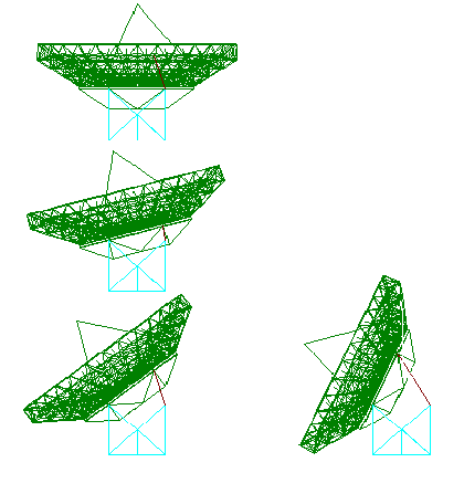
Figure 7 Motion of the 15m telescope in elevation
Although the proposed encoding system is designed on the basis of industrially
available components, it needs to be studied in more detail due to the
extreme requirements, including the master-slave operation of the doubled
servo system. The very good experience with the dual-axis photoelectric
autocollimation system purchased by the NRAO for possible use on the GBT
indicates the accuracy that such instrumentation can achieve, but the system
has not yet been demonstrated on a telescope. The unbalance about the main
axes should not be a major servo problem under the condition that both
drives are correctly designed. Also here, some development work will be
necessary.
This sections discusses the costs of the different telescope designs which have been studied. The costs of quantity production of the various designs has been estimated by the separate engineering groups with an attempt to break the costs down into a consistent set of subcategories. At the October meeting in Socorro the antenna working group went over the cost estimates in each subcategory and tried to rectify discrepancies by applying the same raw material costs for things like steel, concrete, etc. We also filled in various blanks where possible and used improved estimates of items such as the secondary, bearings, etc. The break down in the costs are presented in Table 6 in the Appendix. The total costs along with several cost curves are plotted in Fig. 7. Note that for the 8 m diameter data points are provided for antennas using both CFRP and steel for the reflector backup structure (BUS), with the steel BUS costing about $200K less than CFRP.
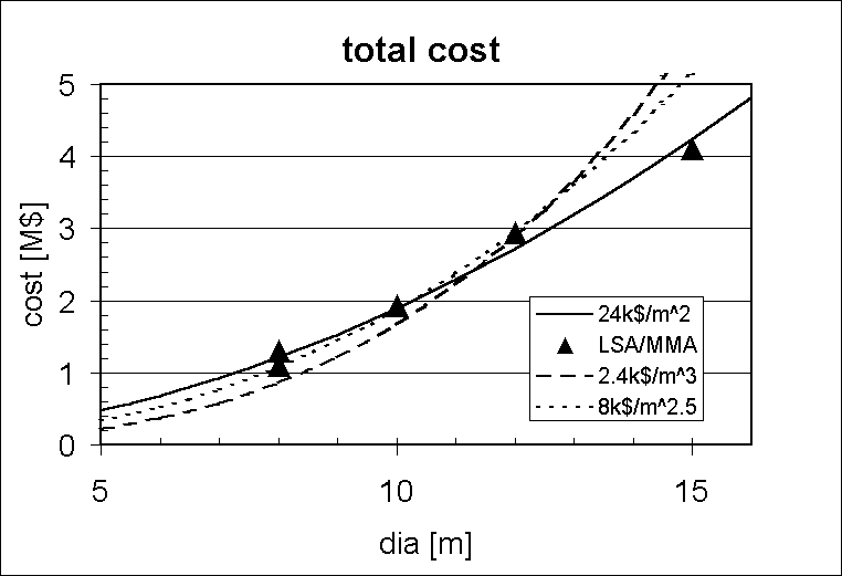
Figure 8. Total Antenna Cost
The 8, 10 and 12 meter designs fall on a D^2.5 curve which has been observed for many other telescope cost studies whereas the 15 meter costs are more consistent with a D^2 curve. The uncertainties in the cost estimates are probably quite large and don't accurately determine a "cost curve". (Note that the best fit to the data is a straight line which intersects zero cost at 5 meter diameter.)
Figure 9 shows the cost of just the reflectors for the various telescope designs, with costs for both a steel and CFRP BUS shown for the 8 m. These costs include all of the tipping structure except the secondary and feedlegs and don't include any of the mount costs. The three smaller designs are consistent with a cost curve steeper than D^3 while inclusion of the 15 meter cost yields D^2.5. (The straight line fit intersects zero cost at 7 meter diameter.) A separate reflector cost study was also carried out by a commercial antenna company. The data from this study was consistent with a D^2 curve over the same range of telescope diameters but with the surface and pointing specifications degrading at the larger diameters.
It should be noted that the total costs include 30% for the costs of a commercial company for administration and overhead and 15% contingency. This is 31% of the total antenna production costs. This represents a significant cost and different procurement methods, such as those used by IRAM for their 15 meter telescopes, might reduce the costs significantly.
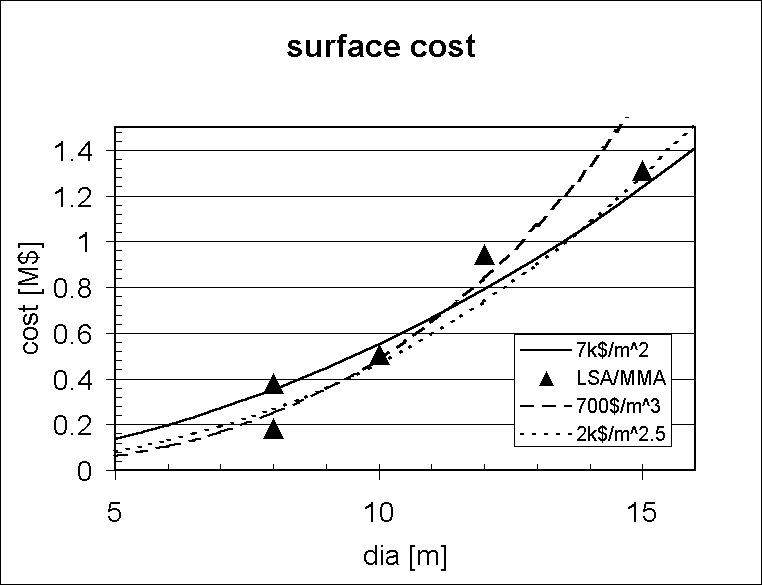
Figure 9. Reflector Cost
As well as the production costs for the antennas, which have been discussed above, it is necessary to consider the one time costs for developing the final design drawings, prototyping and tooling up for the production program. Discussions with commercial antenna companies lead to the following rough estimates for the major one time costs:
Table 5. Estimate of the one-time costs
Most of these costs, except for the assembly building and one time prototype costs which are given for the larger diameter antennas, scale weakly with antenna diameter. They are rather uncertain, however, with factors of two or so difference in the estimates for some items from different commercial companies. The one time prototyping costs are intended to cover such items as additional costs for the first antenna due to small quantity production, special tests of antenna elements, costs to build some components in two different ways to determine the best design, fabrication of special alignment tools such as the surface measurer, rent of an assembly building for the first antenna and transporter prototyping costs. The cost of the first antenna should be budgeted as the production cost from Figure 8, plus the non-recurring engineering cost plus the one time prototyping cost plus the one time tooling cost.
The data is remarkably consistent, considering the large differences in the design approaches used. Thus we probably know the costs for telescopes in the size range from 8 to 15 meters well enough for preliminary budget purposes. But the data do not yield a simple well characterized cost law. This means a global optimization of the array performance vs. cost will not be very definitive. Such optimizations usually produce broad peaks in the diameter range studied here and hopefully an accurate cost curve is not necessary.
The cost curve is not as steep as one might expect considering the difficulty in maintaining the precision of a structure as it is scaled up in size. Simply scaling a design up in diameter and spending more money does not necessarily get you the same performance specifications. A study by a commercial company shows this quite clearly. They scaled the same reflector design from 8 to 12 and 16 meter diameters and the costs ended up scaling as D^2 but the surface rms degraded from 15 to 17 to 25 microns. Thus the 8 meter exceeded the specification while the 16 meter just barely met the specifications.
The larger diameters require more innovative designs and this innovation does not necessarily cost a lot more. What does happen is that the phase space of specifications gets pushed around. That is the basic rms surface and pointing specifications are met but other specifications, such as elevation range, receiver room size, foundation complexity, blockage, etc. changes. The innovation necessarily must increase with diameter if you are pushing the boundaries of what can be done. But what is not clear is whether you can apply the innovative ideas, once they are revealed, to smaller telescopes and save money relative to the more standard designs. The innovation is not expensive and not a way to save money but is necessitated by the design challenges as you increase the diameter.
The designs presented have probably not yet been optimized for cost. We will be building a large number telescopes and can afford to really work on decreasing the cost. Cheaper telescopes means more of them, more collecting area and better imaging. To do this requires understanding the specification very carefully so that the system is not over designed. Exceeding specifications means that you have wasted some money somewhere. Once this is done the cost curve may steepen somewhat. Also the second order specifications (elevation range, complexity, ease of transport, etc.) and the risk or margin in meeting the surface and pointing specifications will degrade as the telescope diameter increases.
It is hoped that the information provided in this report, together with consideration of the scientific issues, will allow a decision to be made concerning the diameter, or diameters, of the antennas for the LSA/MMA array. During this study a number of clever design ideas for millimeter/submillimeter antennas have been identified. Also, the different designers have chosen to emphasize the various performance requirements in different ways. The committee believes that after the final diameter is decided a period of about nine months should be spent optimizing the design before issuing an RFP for the detailed design and fabrication of prototype antennas. This optimization would be done by incorporating the best of the ideas identified during this study and by ensuring that the correct priority is given to the various, sometimes conflicting, performance requirements. This latter process of prioritizing the requirements must be carried out in close consultation with the scientists. The two primary performance requirements for the antenna are pointing accuracy and reflector surface accuracy. Secondary performance requirements which should be considered with respect to their cost and impact on the primary requirements include:
(1) For the smaller diameters, the cost/performance benefit of using CFRP for the reflector backup structure.
(2) Location and shape of the subreflector support legs.
(3) Range of elevation angles accessible to the antenna.
(4) Existence and size of the receiver cabin.
(5) Impact of array reconfiguration time on the design of the interface between the antenna and its foundation.
(6) Use of active metrology to reduce cost or improve performance.
(7) Cost/performance impact of including a subreflector nutator.
From our studies over the last two months we conclude that it is feasible to build antennas with diameters in the range 8 m to 15 m with pointing accuracy of 1/30th beamwidth at 300 GHz and surface accuracy of 25 µm. Our cost estimates for the antennas, as a function of diameter, are shown in Figure 8 above. A simple formula, that is a reasonable fit to this data over the diameter range 8 m to 15 m, is that antenna cost is simply proportional to collecting area at the rate $24K/m2. The relatively low cost of the 15 m antenna results from a number of design innovations, in particular the use of a commercial active laser metrology system which corrects for pointing errors caused by the antenna foundation and mount and allows the cost of these elements to be reduced. Such a metrology system is not yet in use on any existing telescope and needs further development.
As the antenna diameter is increased the margin with which the pointing and surface accuracy requirements can be met is reduced. This means that, as the diameter increases, the designer has less flexibility to optimize for second order requirements such as locating the feed legs for minimum blockage and providing for full sky coverage in the range of elevation angles accessible to the telescope. On the other hand a few requirements, such as the desire for a large receiver cabin, become easier to satisfy for larger diameter antennas.
References
Andersen, T., "Feasibility Study for a 12m Submillimeter Antenna",
ESO, Sept 1997.
Holdaway, M.A. et. al., "Wind Velocities at the Chajnantor and Mauna Kea Sites and the Effect on MMA Pointing", MMA Memo 159, NRAO, http://www.mma.nrao.edu/memos/abstracts/abs159.html, Aug. 1996.
Holdaway, M.A., "Calculation of Anomalous Refraction on Chajnantor", MMA Memo 186, NRAO, http://www.mma.nrao.edu/memos/abstracts/abs186.html, Sept. 1997.
Levy, R., Structural engineering of microwave antennas for electrical,
mechanical, and civil engineers, IEEE Press,1996.
Lucas, R., "Reference Pointing of LSA/MMA Antennas", LSA Study, IRAM,
http://iram.fr/LSA/collab_mma/reports/pointing/pointing.html, Oct. 1997.
Also published as MMAMemo 189, http://www.mma.nrao.edu/memos/abstracts/abs189.html,
Nov, 1997.
Napier, P.J., et. al., "Antennas for the Millimeter Wave array", MMA Memo 145, http://www.mma.nrao.edu/memos/abstracts/abs145.html, Nov. 1995.
Napier, P.J., "Report of the LSA/MMA Antenna Study Group Meeting, 19-21 August, 1997", http://www.nrao.edu/~pnapier/LSAMMA/sept97report.htm, Sept. 1997.
Plathner, D., Bremer, M. and Delannoy, J., "The 15m (12.8m) Telescopes for the MMA/LSA Project", IRAM, Sept. 1997.
Appendix
Itemization of antenna costs for each of the four designs. These are
the quantity reproduction costs and do not include the one time costs of
the prototypes, fixtures, etc. Costs are given in kUS$. There are three
columns for each design. The first column is the quantity with the units
given with the item label such as the number of square meters of panels
or the weight of CFRP. The designs which don't require an item have 0 as
the quantity. Note that it has been assumed that each antenna will need
four different foundations to handle the various configurations. The second
column is the cost basis such as the kUS$ per square meter or kUS$ per
kilogram, and the third column is the net cost for that item. The item
costs are subtotaled into three categories; 1) reflector which includes
the panels, backing structure and tilting structure, 2) subreflector and
feedlegs, and 3) mount and foundation. Then shipping is added to give a
total "material" costs to which administration and contingency are added
as a per centage of the "material" cost with the grand total given on the
last line. The rectification of the initial estimates provided by the designers
was to use similar cost basis for items in common and to fill in blanks
where needed. For the 8m antenna the costs are for a CFRP BUS. The cost
for a steel BUS is about $200K less.
Table 6. Estimated antenna costs