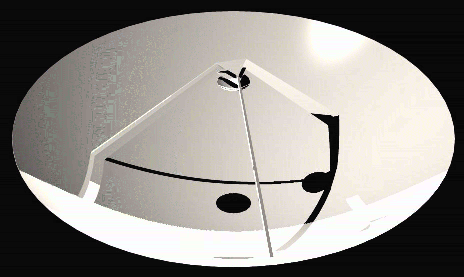
Fig. 1. Structure used in the calculations. The struts have a V shaped profile pointing in towards the center of the dish.
James W Lamb
Owens Valley Radio Observatory
23 January 1998
Abstract: Scattering of ambient radiation into receivers by secondary mirror supports can potentially degrade performance of radiotelescopes. A geometry for the support struts with slanted planar faces to keep scattering sidelobes close to the antenna pointing direction is analyzed. Scattering of the plane wave is within ~15º of boresight, while the spherical wave scattering is within ~1º of boresight. Less than 0.5 K additional noise is predicted. Some other contributions to the antenna noise are also discussed.
I. Introduction
Blockage of the aperture field of a Cassegrain antenna by support struts for the secondary mirror has two adverse effects. One is the reduction of the aperture efficiency by an amount approximately equal to twice the fractional area blocked. The other is the increase in antenna noise temperature due to scattering of the radiation into the feeds from ambient surroundings. If the total aperture blockage is, say 3%, the aperture efficiency is reduced by ~6% and the increase in noise temperature could be as much as 9 K. For the extremely low receiver noise temperatures anticipated for the mmA the latter effect may be the more significant.
The overall strut geometry is determined largely by the mechanics of the structure. It is required to be stiff enough to avoid bending under wind loading and gravity (except, possibly for a homology component). It should also not have any resonances at frequencies that may be excited by the drive system or wind. The size and general arrangement for the struts must therefore be optimized structurally, but the detailed shape can be designed to minimize scattering of radiation at large angles to the boresight where it may fall on ambient temperature surroundings.
Some design aspects are examined below to estimate blockage and noise degradation.
II. Mechanical Considerations
A. Support Configuration
Generally the support for a secondary mirror comprises a number of struts of uniform cross-section passing through the primary and attached to a mount supporting the secondary. The lowest natural mode of the whole support structure is generally a twist round the optical axis. In some antennas such as the JCMT and Voyager spacecraft, the support structure is similar to those of optical telescopes, with the supports arranged as triangular frames. This gives higher rigidity but also greater blockage [1]. Other antennas such as the OVRO 10-m and the NRAO 12-m have guy wires added to give torsional stiffness. The rotational mode may be excited if there are large azimuthal accelerations when the antenna is at high elevations but there should be little coupling with secondary mirror nutation and wind loading, for example. If a CFRP structure is used the natural damping will be higher than for a steel structure. Optically, the first order effect of this rotation is zero since the secondary mirror is nominally on the rotation axis. Small pointing shifts could result from asymmetry, and path length changes appear as a second order effect.
The stiffness of the structure depends on the strut dimensions. Torsional stiffness is proportional to the strut depth (radial direction), the cube of the width (azimuthal direction) and the inverse of the length. Since shadowing is not affected by the strut depth this may be quite large. The most critical choice is the width which strongly affects the blockage and stiffness.
Conventional structures use two, three, or four struts. The 2-strut solution is worse in the sense that it requires guy wires which stress the structure asymmetrically, but there are not major differences between the 3- and 4-strut solutions. For a given torsional stiffness the 3-strut solution has ~17% lower blockage. The choice of the number of struts may also be influenced by the symmetry of the backing structure.
B. Strut Attachment Point
For minimum blockage with a given strut width the fixture points should be at the rim of the primary mirror to avoid blockage of the spherical wave. This has been used on smaller antennas (e.g., OVRO 5-m, BIMA 6-m), but is not necessarily a good structural solution for larger antennas (e.g., OVRO 10-m, NRAO 12-m, JCMT 15-m, VLBA 25-m, Bonn 100-m), and an attachment diameter of 0.50.8 of the primary mirror diameter is more common. However, since the strut length is reduced, the strut width may be decreased for the same stiffness and the blockage penalty is minimized. Narrower base attachment makes the structure much more rigid as the bending stresses are decreased in favor of longitudinal compression stress.

Fig. 1. Structure used in the calculations. The struts have a V shaped profile pointing in towards the center of the dish.
Following the above arguments we choose a structure with three struts (Figs. 1, 2), radially oriented, and the base attached at about Rs = 0.325D, where the dish diameter D, is 10 m. The angle to the vertical, b , is about 44º, giving a horizontal distance from the focus, Rf, of about 0.58 m. No attempt has been made to optimize the structure as this will be part of the detailed structural modeling. However, the values are probably reasonable from the mechanical point of view. The struts are thicker in the radial direction than in the azimuthal one as this has no effect on the blockage. The strut profile is discussed later. Fig. 1 shows a rendered view of the design assumed for this study, and Fig. 2 gives the coordinate system and parameters referred to further on.
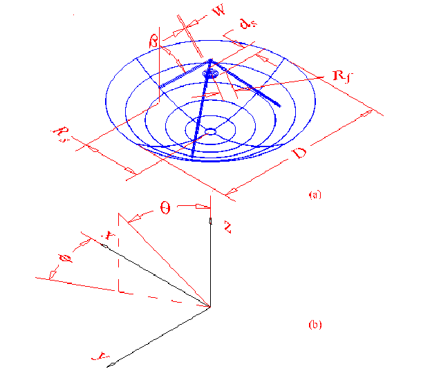
Fig. 2. (a) Parameters of the antenna and secondary mirror referred to in the text. The strut width, w, is given in the azimuthal direction. (b) coordinate system for the calculations.
III. Blockage and Spillover
A. Blockage
For the short wavelengths of the mmA a geometrical optics calculation of the blockage is sufficiently accurate. When the struts are not attached at the rim of the primary they block both the plane wave from the aperture and the spherical wave from the secondary to the primary. The plane wave shadow is the projection of the struts on the aperture plane, and appears as radial shadows of the same width as the struts. The spherical wave shadow starts at the base of the strut and broadens out to the edge of the aperture [2]. The width at the edge depends on the distance of the strut from the prime focus along the geometrical edge ray. To keep this narrow, the top of the supports should be as far out from the axis as is structurally reasonable. In this strawman design we also taper the strut width, w, from about 80 mm at the base to about 50 mm at the top which gives a useful increase in stiffness with a small increase in blockage.
We have computed the blockage analytically, as well as using the Ray Trace Rendering capabilities of AutoCAD to determine the shadowing in the aperture plane (Fig. 3). The bitmap can be imported into Mathcad to calculate the area lost to blocking. This method can be used for any support geometry desired. With a secondary mirror diameter of 700 mm the total shadowing is ~2.6 % (2.8 % with aperture weighting). Of this, the struts contribute ~1.9 % (1.8 % with weighting). The maximum possible contribution to the antenna noise temperature by strut scattering is therefore ~5.5 K, though even with non-ideal structures we expect much less than this.
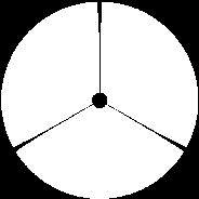
Fig. 3. AutoCAD ray tracing of the aperture plane shadow.
B. Scattering
There have been several publications that predict the distribution of scattered radiation but these have generally been concerned with struts having widths comparable to a wavelength [3][6]. Rusch et al. [3] show that the scattering of a plane wave by a cylindrical member is in a conical pattern, with the cone axis along the strut and the cone half-angle equal to the angle of the strut to the plane wave direction. This is illustrated in Fig. 4. The distribution of the radiation round the cone is complicated, but it may be shown that it approaches the geometrical optics limit for short wavelengths. Provided the strut has the same cross-section over its length the scattering will still be in this conical pattern and only the variation of amplitude around the cone changes.
Instead of assuming cylindrical members, we take struts with a triangular inner surface. This profile has been proposed and used in several antennas, mainly as a retrofitted modification (see [4][7], for example). Fig. 5 gives the strut profile and the relevant dimensions.
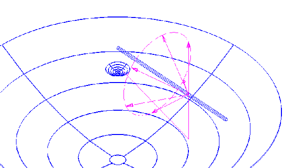
Fig. 4. Conical scattering direction of the plane wave by a strut.
Plane Wave Scattering
If the half-angle of the triangle is a and the strut is parallel to the plane wave with the V facing it, the field will be scattered by an angle 2a . As the strut is raised relative to the wavefront the deviation angle will be decreased towards zero when the strut is vertical. With the notation of Fig. 2 and Fig. 5, the angle of the scattered beam relative to boresight (corresponding to a single ray in Fig. 4) is, for small a
 (1)
(1)
at an azimuth relative to the strut position of
 (2)
(2)
The ± is for the two sides of the V. If we take a = 10º then we find that the scattering is at an angle of ~14º to the optical axis and an azimuth angle of ± 97º relative to the strut. The spread of the scattered beam is at least the diffraction spread of the projection of the strut on the wavefront. That is, it will be
![]() (3)
(3)
by
![]() (4)
(4)
For a wavelength of 3 mm this gives ~0.1º ´ 6º. Since the legs will not be perfectly flat the scattering will be broader than this in practice. Indeed it may be preferable to introduce a wider scatter to reduce the peak intensity.
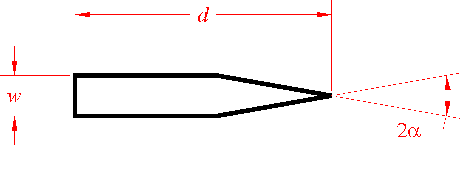 Fig. 5. Cross-sectional profile of the strut used in the text. The strut depth, d, does not affect the scattering or blockage.
Spherical Wave Scattering
Little study has been published on the scattering of the spherical wave ¾ often the struts are attached at the rim of the primary so it is not an issue. In the model here about 47% of the strut blockage is of the spherical component so it represents a significant part of the loss budget. For cylindrical struts the scattered radiation can be considered to be composed of cones corresponding to rays at different angles to the axis, as illustrated in Fig. 6. Clearly all the radiation strikes the primary and is reflected in the forward plane. Although reasonable estimates of the reflected radiation for cylindrical members may be made we will consider only the triangular-section struts. Fig. 6. Scattering of a spherical wave ray passing from the secondary mirror towards the primary.
In Fig. 6 the strut is shown as scattering the field all round the cone. With the V shaped front on the strut it will be reflected in only two directions symmetrically about the strut. Rather than tracing rays we can determine the position of the image of the primary focus in the reflecting face of the strut. By using conventional formulas for beam shift we can then find the direction of the beam after it hits the primary.
We find with some geometry that the image of the prime focus is laterally shifted in the focal plane relative to the primary by a distance d r given by
![]() (5)
(5)
at an azimuth angle relative to the strut of
![]() (6)
(6)
(The ± is again for the two sides of the V). The defocus in the z-direction is
![]() (7)
(7)
Since the image of the focus is displaced from the focal point the beam after reflection from the primary will be in a direction qs relative to the optical axis, found from
![]() (8)
(8)
where BDf is the prime focus beam-deviation factor [8] and is typically in the range 0.60.8. The azimuth relative to the strut direction is
![]() (9)
(9)
For our model we therefore have qs = 1º from boresight and an azimuth relative to the strut of s = ± 187º. Note that the main beam width at l = 3 mm is 0.02º.
After reflection by the primary the beam shape will be roughly the same as half the outer part of the shadow pattern shown in Fig. 3 (half since there are two reflecting faces on the V). The width of the radiated pattern is determined by the amplitude and phase distribution over this area. If it were uniformly illuminated with constant phase the angular widths of the pattern parallel and perpendicular to the shadow direction would be
![]() (10)
(10)
where w is measured a the base of the strut, and
![]() (11)
(11)
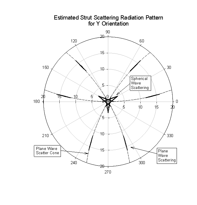 Fig. 7. Estimated of the distribution of the radiation scattered by the support struts. The wavelength is 3 mm. On this scale the main beam is too small to be visible.
The inverted-Y configuration is marginally better than the Y, but at a level which would be difficult to detect.
C. Other Sources of Ambient Pickup
In addition to the strut scattering, radiation may be picked up by panel gaps, secondary diffraction, reflection from the secondary through the hole in the primary, and ohmic losses.
Panel Gaps
For reasons of thermal expansion and assembly, gaps between panels typically need to be 12 mm per meter of panel size. This translates into a fractional area of 0.20.4 %. Although the gaps are small compared to the wavelength, the effective area averaged over the two polarizations is close to the physical area [9]. We therefore expect 0.51.2 K from this source.
Secondary Diffraction
Diffraction at the secondary induces pick-up round the primary. Previous studies [10] indicate about 1 K increase in antenna noise temperature for a 750 mm diameter secondary at 3 mm wavelength. This will increase for smaller secondaries. Reducing the secondary size from the geometrical limit or extending the primary with a skirt could reduce this, but the size of the diffraction pattern at the primary is of order 0.3 m at a wavelength of 3 mm.
Re-radiation Through Central Hole in Primary
Reflection and diffraction from the secondary through the central hole in the primary can be kept much lower than 1 K with suitable modification to the center of the secondary mirror, such as the addition of a shallow cone.
Ohmic Losses
For two good aluminum surfaces the loss at some frequency n on reflection is expected to be about [11], [12]
![]() (12)
(12)
so associated noise is ~1 K at 100 GHz and ~2 K at 300 GHz.
Table I summarizes these results.
|
source |
contribution, K |
comments |
|
strut scattering panel gaps central blockage secondary diffraction ohmic losses |
<0.5 |
frequency independent, El > 15º frequency independent with cone µ l -1/2, El dependentµ l 1/2 |
|
total |
36 |
|
IV. Discussion
Although it has often been assumed that the support structures for secondary mirrors should be attached to the rim of the primary mirror to minimize blockage this is not, in practice an optimum choice. By bringing the attachment points in, shorter (and therefore narrower) struts may be used reducing the blockage. With a triangular strut profile the scattering may be kept relatively close to the optical axis of the antenna. Again the narrower base is beneficial since it brings the plane wave scattering closer to boresight and moves the spherical wave scattering away from the main beam.
Some diffraction effects are included in the above treatment but the effects of discontinuities in the physical optics currents are not included. Since these effects occur within ~
l of the discontinuities, such as the apex of the strut V, they correspond to an extremely small fraction of the radiation fields. The integrated effect is therefore completely negligible in the noise budget. In addition, the effects averaged over two polarizations are typically equal to the geometrical optics calculations as we noted for the panel gap scattering.The design considered here was not optimized structurally or optically, but clearly very low pick-up of ambient radiation and low blockage may be achieved with a range of parameters. Final optical design may be done during the final structural design.
References
[1] J.W. Lamb and A. D. Olver, "Blockage due to subreflector supports in large radiotelescope antennas," IEE Proc., vol. 133, Pt. H, no. 1, pp. 4349, Feb, 1986.
[2] J. Ruze, "Feed support blockage loss in parabolic antennas," Microwave J., vol. 11, no. 12, pp. 7680,1968.
[3] W. V. T. Rusch, O. Sørensen and J. W. M.Baars, "Radiation cones from feed-support struts of symmetric paraboloidal antennas," IEEE Trans. Antennas and Propagat. Vol. AP-30, no. 4, pp. 786790, July 1982.
[4] T. L. Landecker, M. D. Anderson, D. Routledge, R. J. Smegal, P. Trikha, and J. F. Vaneldik, "Ground radiation scattered from feed support struts: A significant source of noise in paraboloidal antennas," Radio Science, vol. 26, no. 2, pp. 363373, MarchApril 1991.
[5] T. Satoh, S. Endo, N. Matsunaka, S. Betsudan, and T. Katagi, "Sidelobe level reduction by improvement of strut shape," IEEE Trans. Antennas Propagat., vol. AP-32, no. 7, pp. 698705, July 1984.
[6] F. J. S. Moreira, A. Prata, and M. J. Thorburn, "Minimization of the plane-wave scattering contribution of inverted-Y strut tripods to the noise of reflector antennas," IEEE Trans. Antennas Propagat., vol. 44, no. 4, pp. 492499, April 1996.
[7] C. R. Lawrence, T. Herbig, and A. C. S. Readhead, "Reduction of ground spillover in the Owens Valley 5.5-m telescope," Proc. IEEE, vol. 82, pp. 763767, May 1994.
[8] J. Ruze, "Lateral-feed displacements in a paraboloid," IEEE Trans. Microwave Theory and Tech., vol. AP-13, pp 660665, 1965.
[9] E. V. Jull, Aperture Antennas and Diffraction Theory, Oxford: Pergamon Press, 1990.
[10] J. W. Lamb and A. D. Olver: "Gain loss and noise temperature degradation due to subreflector rotations in a Cassegrain antenna," Proc. Int. Conf. Antennas Propagat. 85, April 1985.