(1) - National Radio Astronomy Observatory, Socorro, New Mexico, USA
L. Kogan![]()
(1) - National Radio Astronomy Observatory, Socorro, New Mexico,
USA
Different configurations have been offered ([2],[3], [4])), using the method of optimization of an array configuration minimizing side lobes ([1]). It is supposed that the lower the level of side lobes the better restored image should be. This memo demonstrates the advantage of minimum side lobes in the quality of the restored images. The UV data were simulated (with the new AIPS task UVCON) for two arrays: optimum (by minimum side lobes) and not optimum with the same number of elements (36). The most compact configuration (D) has been considered. The simulation was made for three classes of model: 1. Several close compact components; 2. Many wide spread out compact components; and 3. One expanded complex component (CAS-A). The different noise was added at simulation. The images were restored from the simulated UV data by AIPS task IMAGR. The restored images for optimum and not optimum configuration for different added noise are shown. In all cases the optimum configuration gives better image fidelity. The simulation should be continued for other configurations (A, B, C) with the number of the array elements equal 48 corresponding the combined MMA/LSA project.
Different criteria of arrays design can be considered. One of the most popular criterion is a good UV coverage. This criterion is very subjective because it is difficult to measure quantitatively the quality of the UV coverage. Last time the criterion of minimum side lobes has been used to optimize the array configuration ([1],[2],[3], [4])). This criterion is simple estimated quantitatively. Some people considered that CLEAN is so powerful that it can clean any side lobes if the beam pattern is known. Practically it can not be true because of the gridding and noise problem. If it were true, the array of only two elements could solve all problems. The final conclusion of an array configuration quality can be done comparing the quality of the restored images. This memo gives the result of simulation of UV data for optimum (by minimum side lobes) and not optimum array configuration to demonstrate the better restored image of the optimum configuration.
Both optimum (Figure 1) and not optimum (Figure 2) configurations have a circular shape with diameter 95 meters. The optimum configuration is taken from MMA memo 226 ([4]). The elements of the not optimum configuration are located homogeneously on the circumference. The plot of the beams of the arrays for wavelength ![]() are given at the figures 3 and 4. It is seen from the plots that side lobes of the optimum array are less 10% inside of the optimization area - the circle of radius
are given at the figures 3 and 4. It is seen from the plots that side lobes of the optimum array are less 10% inside of the optimization area - the circle of radius ![]() ; while the not optimum array has the side lobes more than 25%. The recently written AIPS task UVCON was used to simulate UV data. UVCON allows to give the position of the array elements at different coordinate system. I used the orthogonal coordinate system at the plane perpendicular to the local zenith of the array site. To calculate the simulated noise in Jy, the parameters of each antenna (diameter, efficiency, noise temperature) are given at the input file together with the antenna coordinates. The bandwith and time average are given also to evaluate rms of the noise. Finally the level of the noise (in Jy) was selected near the minimum visibility amplitude. The model can be given as image or as clean componnents given in CC table. The parameter wavelength allows to simulate different angular resolution.
Snapshot observation with the latitude of the site
; while the not optimum array has the side lobes more than 25%. The recently written AIPS task UVCON was used to simulate UV data. UVCON allows to give the position of the array elements at different coordinate system. I used the orthogonal coordinate system at the plane perpendicular to the local zenith of the array site. To calculate the simulated noise in Jy, the parameters of each antenna (diameter, efficiency, noise temperature) are given at the input file together with the antenna coordinates. The bandwith and time average are given also to evaluate rms of the noise. Finally the level of the noise (in Jy) was selected near the minimum visibility amplitude. The model can be given as image or as clean componnents given in CC table. The parameter wavelength allows to simulate different angular resolution.
Snapshot observation with the latitude of the site ![]() was simulated.
Having created the UV data, the AIPS task IMAGR was used to restore the image.
The restored image was compared with the model. The result of the comparison for three models are given further.
was simulated.
Having created the UV data, the AIPS task IMAGR was used to restore the image.
The restored image was compared with the model. The result of the comparison for three models are given further.
The image of the first model is given at the plot (5). The image was obtained with VLA observation with angular resolution ![]() . The UV data were simulated with wavelength 0.1mm to have approximately the same angular resolution with the considered arrays of diameter 95 meters. The plots of the restored images for the optimum and not optimum arrays for different added noises are given at figures:
(6, 7). Looking at the plots everyone can say that the optimum array gives better image fidelity in comparison with the not optimum one.
. The UV data were simulated with wavelength 0.1mm to have approximately the same angular resolution with the considered arrays of diameter 95 meters. The plots of the restored images for the optimum and not optimum arrays for different added noises are given at figures:
(6, 7). Looking at the plots everyone can say that the optimum array gives better image fidelity in comparison with the not optimum one.
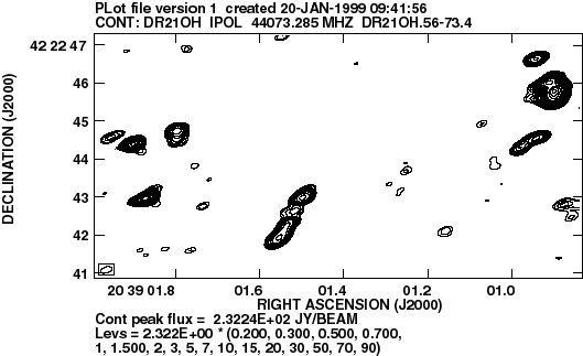
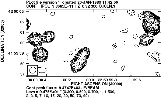
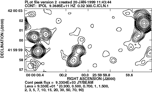
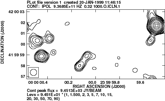
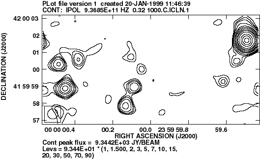
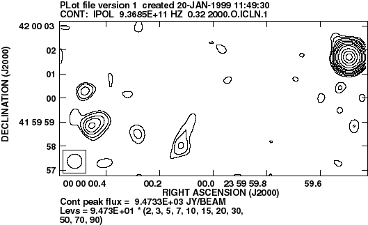
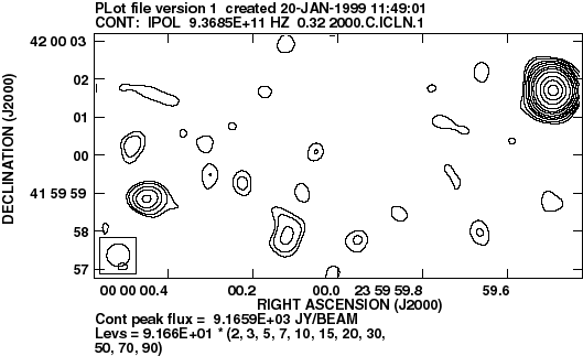
The image of the second model is given at the plot (8). This image includes the image of the first model (the most left part) and differed from the first model by more number of components and wider range in the space. The UV data were simulated with wavelength 0.32mm. The more wavelength was selected to guarantee the image at least twice less the area of optimization of the side lobes (see figure 3). The plots of the restored images for the optimum and not optimum arrays for different added noises are given at figures: (9, 10, 11, 12, 13, 14). And again the optimum array gives better image fidelity in comparison with the not optimum one.
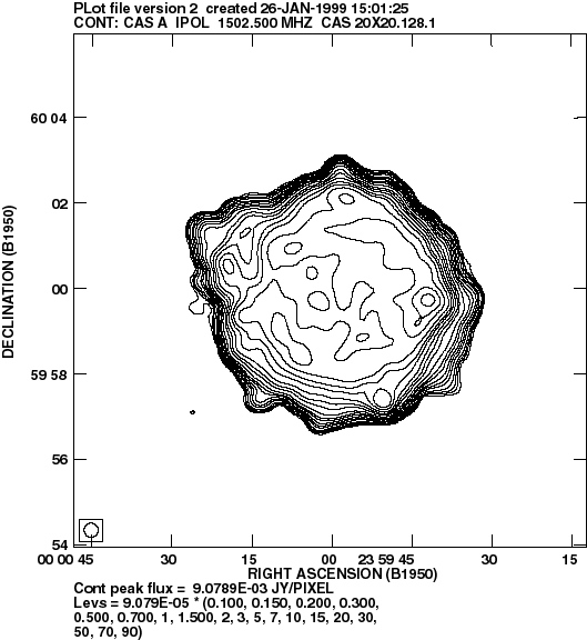
The image of the third model is given at the plot (15). This image has been obtained by smoothing CAS-A image observed at VLA. Because the optimum configuration was design with constrain of minimum spacing 12.8 meters, the UV coverage has the hole of radius 12.8m at the center. The expanded structure can have more information inside of this hole. The compared not optimum array does not have the minimum spacing constraint. That is why the central hole is less for this configuration. To eliminate this difference i.e. to prevent loosing information in the hole we need to satisfy the following inequalities:

whereThe size of the array configuration isis the wavelength
is the minimum baseline
is the maximum baseline
is the size of the expanded feature
is the angular resolution.
The provided simulation shows that an array with minimum side lobes gives the better image fidelity for the three considered classes of the sources. The simulation was provided for the most compact configuration of MMA. The simulation should be continued for other configurations (A, B, C) with the number of the array elements equal 48 corresponding to the combined MMA/LSA project and other source models including tracks due to the Earth rotation.


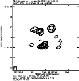 |  |
| Figure 6: The image obtained using the optimum (left) and not optimum configuration (right). Noise = 1Jy. All main components of the original model (figure 5) are seen in the simulated image with optimum configuration. Some components of the original model (figure 5) are not seen in the simulated image obtained with not optimum configuration (right plot). The image with not optimum configuration is more noisy. | |
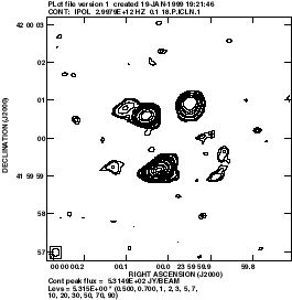 |  |
| Figure: The image obtained using the optimum (left) and not optimum configuration (right). Noise = 18Jy. All main components of the original model (figure 5) are seen in the simulated image with optimum configuration. Some components of the original model (figure 5) are not seen in the simulated image obtained with not optimum configuration (right plot). The image with not optimum configuration is more noisy. | |
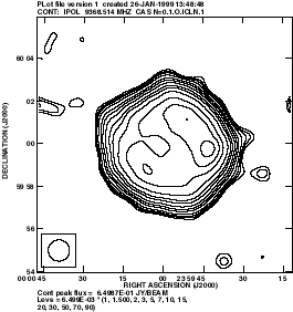 |  |
| Figure 16: The image obtained using the optimum (left) and not optimum configuration (right). Noise = 0.1Jy. The image corresponding the optimum configuration shows better fidelity relatively of the original model (figure 15) . The image with not optimum configuration is more noisy. | |
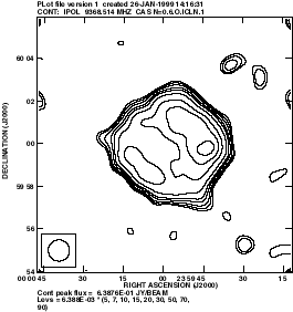 |  |
| Figure 17: The image obtained using the optimum (left) and not optimum configuration (right). Noise = 0.6Jy. The image corresponding the optimum configuration shows better fidelity relatively of the original model (figure 15) . The image with not optimum configuration is more noisy. | |