ALMA Strawperson Zoom - C Array Equivalent
Physical Descriptions:
- Maximum baseline 1068 m
- Minimum baseline 15 m
- Maximum near-in sidelobe 2%
Antenna Positions:
Antenna positions are given here in meters
in UVCON format . The X and Y positions
are with respect to a reference position on the 5 degree mask.
To convert to SAM56 coordintes:
SAM56 E = 628340 + X
SAM56 N = 7453250 + Y
Array Layout, UV Distribution :
(left panel) Pad distribution superimposed onto terrain and uv coverage.
(Middle panel) Pads (open circles) and antennas (filled circles) superimposed
on the 5deg gradient mask.
(Middle panel) UV coverage and distribution of pad density versus
radius. Yellow line indicates best fitting gaussian.
Beams, Snapshot and 4hr synthesis :
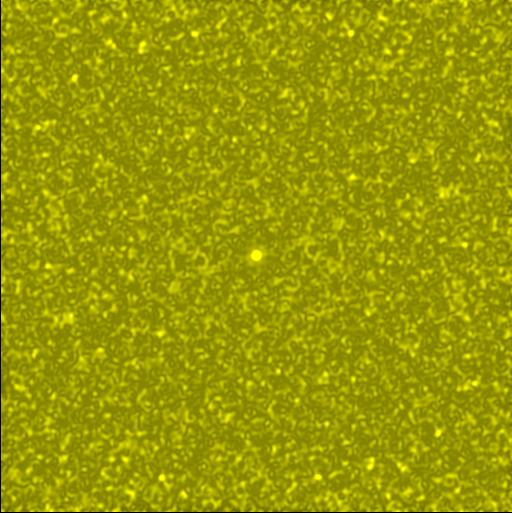
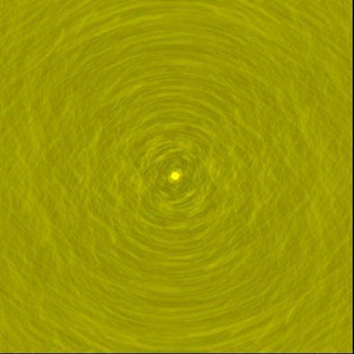
(Left panel) Zenith snapshot dirty beam.
The plotted grayscale ranges between -5% and +10%. The
peaks sidelobe between radii of 1 and 22 beams is 0.0508.
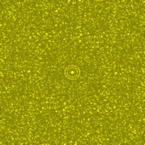
(Right panel) Long track dirty beam for a dec=-23 sources observed
+/-2hrs from transit. Note all antennas weights assumed equal and
image is naturally weighted. The peak sidelobe within 20 beams
is 0.0276.
Comparsion beams for the twin ring strawperson design:
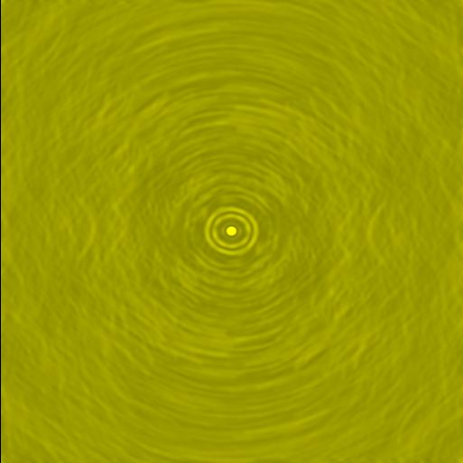
(Top Left) Zeniith snapshot dirty beam.
The plotted grayscale ranges between -5% and +10%.
(Right panel) Long track dirty beam for a dec=-23 sources observed
+/-2hrs from transit. Note all antennas weights assumed equal and
image is naturally weighted. The peak sidelobe within 20 beams
is 0.0469.
Comparsion uv density distributions for snapshots:
Comparison between the zoom and double ring uv coverages. Blue
refers to the zoom design and red to the double ring design.
About 1.2% of the zoom arrays' uv points lie beyond the maximum
baseline of the double ring array.