 |
It is not practically feasible to place antennas at any location in our science preserve. Topographic constraints cause large areas of the science preserve to be undesirable for antenna placement, due to the cost of putting antennas in those locations. In addition, the existing pipelines and roads provide further constraints for possible antenna locations. Given the guidance of the report of the review committee from the configuration PDR (Guilloteau et al. 2001), a new antenna location mask specifying where antennas should not be placed on the preserve has been created for use by those designing the ALMA configurations, and is presented herein.
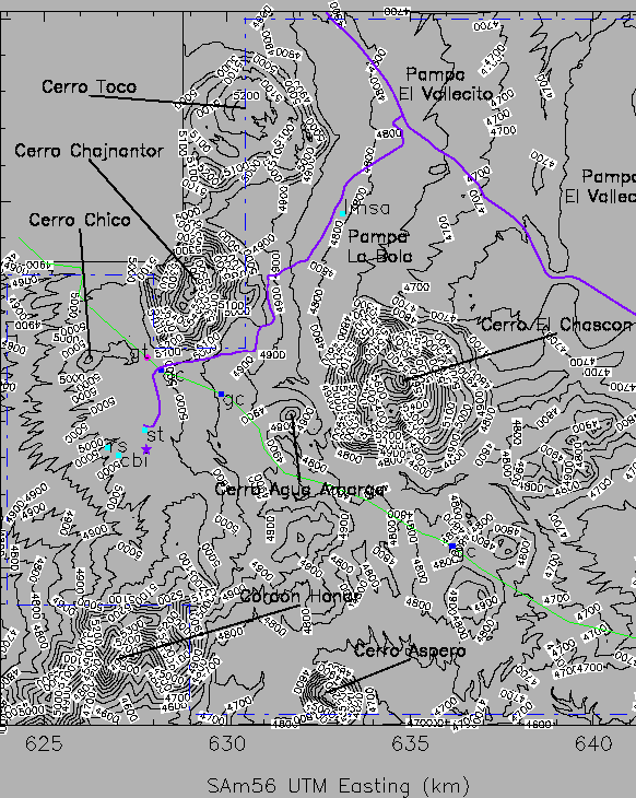
In this memo the entire area for which high resolution (10 meter per pixel) digital maps exist is considered, which encompasses the entire extent of the current science preserve. This study area is roughly bounded by UTM coordinates 624000 - 642000 E and 7446000 - 7465000 N (SAm56 datum; Radford 1999). Figure 1 shows the study area, along with the topography (taken from the work of Holdaway et al. [1996] and recent extensions of that work), and some landmarks.
|
In choosing the possible locations of antennas, many things must be considered, including accessibility, thickness of surface weathering layer (because of implications on foundation construction), proximity to the gas pipeline, shadowing by nearby volcanic peaks, and local terrain (slope). Most of the locations in the study area are equally easily accessible, so that is not considered as a limiting constraint. There is only currently limited information on the how the weathering layer thickness varies with location within the study region (see the NRO-NRAO Geotechnical Report in LMSA memo 2000-04), so that consideration is not treated further here. We note, however, that the thickness of the weathering layer may have a large impact on construction cost, and so a more complete study of both the variation of the thickness of the weathering layer across the entire science preserve, and its impact on construction cost is needed. Areas which are too close to the boundary of the science preserve are excluded from consideration. We take 150 m as an acceptable distance from the boundary, but no closer. Each of the other considerations will now be discussed in more detail.
The Gas Atacama (GA) pipeline cuts through our study area from the southeast to the northwest. The current agreement with GA is to not build within 400 m of the pipeline. However, it has become apparent in recent discussions that it is likely that construction will be allowed to within 100 m of the pipeline. That 100 m distance has been adopted for this study. Note that this follows the recommendation of the configuration PDR review committee. So, locations in the study area closer to the pipeline than 100 m were excluded from consideration for antenna locations. There is another gas pipeline (built by Norandino) which runs approximately parallel to the Jama highway, to the north and east of it. There is no formal agreement with respect to building next to this pipeline (or the Jama highway for that matter), but it seems reasonable that there should be a similar distance from that pipeline to any antennas. The coordinates for that pipeline have not been measured well, so rough coordinates for the Jama highway are used as a proxy for the pipeline coordinates (provided by S. Sakamoto). In addition, it was recommended by the configuration PDR review committee that locations to the north and east of the Jama highway should be avoided if at all possible. This is to avoid possible complications in crossing the highway and pipeline (no specific pipeline crossings were constructed along the Norandino pipeline like the three crossings along the GA pipeline in the science preserve). That recommendation has been followed, and these locations marked as inappropriate for antenna placement.
The study area contains many tall volcanic peaks, which will
provide obstacles to observing astronomical objects at low elevations
(and particular azimuths). The shadowing at every location in the
study area due to all other locations in the area has been calculated.
Locations which are shadowed by 25![]() or more in any direction,
and those which are shadowed by 15
or more in any direction,
and those which are shadowed by 15![]() or more to the north (which
is defined here as within 30
or more to the north (which
is defined here as within 30![]() of true north) are excluded from
consideration for antenna locations.
of true north) are excluded from
consideration for antenna locations.
Antennas should be placed in locations that are as flat as possible.
Places that are too steep will make construction more difficult and
hence more costly. The surface tilt angle is used here as a measure of
steepness, and is defined as the deviation from vertical of the normal
of the plane containing three given surface elevations. This angle is
calculated for each pixel by considering the elevation for that pixel
and the elevations for the pixels adjacent to it to the north, east,
and northeast. Given these four pixel elevations, the four possible
triangles are formed, and the tilt angle of each of these triangles
(which can be thought of as the tilt angle of the plane which passes
through the three points of the triangle) is calculated. The tilt
angle of the pixel under consideration is then assigned to be the
largest of those four tilt angles. One additional test is then
performed - if the angle between any two of these four tilt
angles is larger than the maximum of the four tilt angles, then the
tilt angle for the pixel is assigned to be that angle. This can be
considered as a crude small-scale roughness test. Note, however, that
this occurs for only about 0.1% of pixels which end up in the final
antenna location mask, a very small number. Another way of explaining
this is to consider five unit vectors - the normals of the four unique
triangles given the four surface elevations, and an additional vertical
vector. Now, take the ten unique inner products of these five vectors,
and the tilt angle for the pixel is taken to be the cosine of the
largest of the inner products. A location (pixel) is considered not
appropriate for an antenna location if the tilt derived as described
above is ![]() . This follows the recommendation of the
configuration PDR review committee.
. This follows the recommendation of the
configuration PDR review committee.
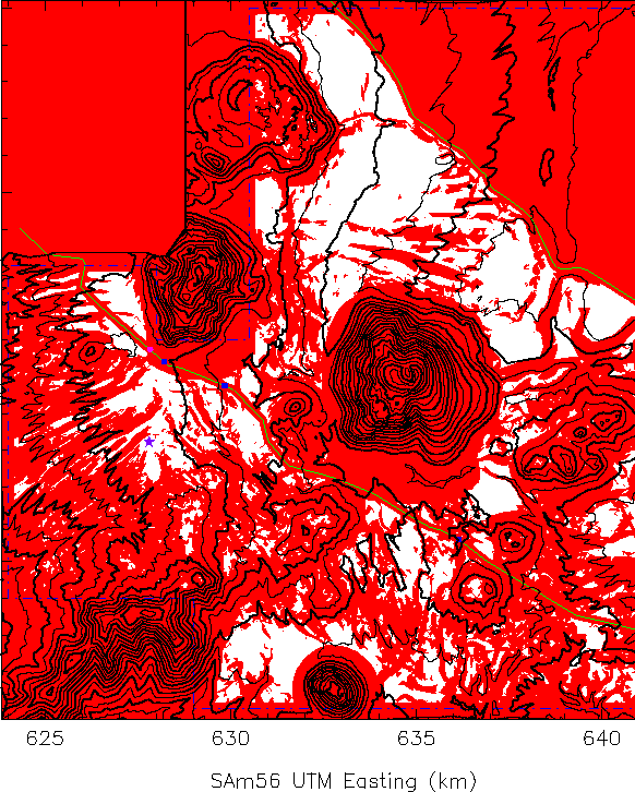
The antenna location mask derived by applying the above constraints is shown in figure 2. This mask can be obtained from the author as a FITS file, with 1's where antennas can be placed, and 0's where antennas should not be placed.
 |
Guilloteau, S., & the Configuration PDR Review Committee, Recommendations of the Configuration Preliminary Design Review, 2001
Holdaway, M.A., M.A. Gordon, S.M. Foster, F.R. Schwab, & H. Bustos, Digital Elevation Models for the Chajnantor Site, MMA Memo. No. 160, 1996
Radford, S.J.E., Position of MMA Equipment on Chajnantor, MMA Memo. No. 261, 1999
This document was generated using the LaTeX2HTML translator Version 2K.1beta (1.50)
Copyright © 1993, 1994, 1995, 1996,
Nikos Drakos,
Computer Based Learning Unit, University of Leeds.
Copyright © 1997, 1998, 1999,
Ross Moore,
Mathematics Department, Macquarie University, Sydney.
The command line arguments were:
latex2html -split 0 -no_navigation mask
The translation was initiated by Bryan Butler on 2001-04-19