Back to Memolist
MMA Memo 202:
Optimization of an Array Configuration with a Topography Constraint
L. Kogan(1)
(1) - National Radio Astronomy Observatory, Socorro, New Mexico,
USA
Abstract:
Algorithm of the optimization of an Array configuration described by
L. Kogan in [1] has been enhanced by the ability to follow a
topographical constraint. The area of the optimization is selected as
a circle of the given radius on the sky. The analysis is provided for
a snapshot observation at zenith. For any other direction of the
source in snapshot observations, the value of the worst sidelobe will
be at least the same. The fitting of the 3.2 km array to the actual
topography of the Chile site is given as an example.
The achieved minimum worst sidelobe practically coincides with the
minimum obtained after optimization without any topography constraint.
Algorithm of the optimization of an array configuration is described by L. Kogan in [1]. The algorithm allows to achieve any small value of the array pattern at the given direction. But minimizing sidelobe at the given direction, the new, perhaps even larger, sidelobe can appear at the different direction. That's why, the software written in AIPS frame uses iteration process.
At each iteration, direction of the worst sidelobe at the given range of the directions at the sky is found. Then each element of the array is shifted to provide a small decrease (under control of input parameter GAIN) of the worst sidelobe. The direction and the value of the shift is found by the algorithm. The new direction of the worst sidelobe is found and the new configuration is found to suppress the new worst sidelobe. The iteration process continues the given number of iterations.
The algorithm supposes the position of elements are normalized, i.e. they are located inside the circle of radius 0.5. The relevant UV coverage occupies the circle of radius 1. The area of optimization in the sky is the circle of radius
N. If the size of the actual array R times bigger, then the radius of the circle of the optimization is determined by the following formula:

where R is the actual size of the array;  is the wavelength
R and  should be taken at the same units of length
I applied optimization for the 36 elements array in snapshot observation at zenith. Change of the source direction in snapshot observation provides linear transformation of the array projection at the picture plane of the source. Such a linear transformation changes the location of the sidelobes but does not change its values. Let's prove it once more. Suppose array's elements position are determined at the plane X, Y. The source direction is determined by asimuth A and elevation h. Both azimuth and elevation are fixed, because we are speaking about snapshot observations. So we can direct axis X at the azimuth of the source. Then unit vectors  and
and  at the picture plane of the source are determined at the selected coordinate system as
  ;
;  . The beam pattern is determined by the sum of complex exponents with power

where eu, ev are projections of a vector at the picture plane on axes u and v
 coordinates of i-element of the array at its plane.
It is obviously seen from the equation (2), that the power of the exponents at the given elevation coincides with zenith ( ) for another position of the pixel at the picture plane of the source:
 .
.
This means that if we have optimized the sidelobes at zenith inside of the circle of radius RC, the sidelobes at the given elevation are not worse at least inside this circle. In fact they are identical at the ellipse with minor axis RC and major axis 
Therefore it is enough to optimize sidelobes at the zenith.
As an example I have provided optimization of 36 elements array inside of circle
of radius 40 resolution elements. ( N = 40 at the equation (1)). The minimum achieved sidelobes is 0.126.
The new software has been written to fit a given array to the given topography.
The fitting process includes two stage:
1. The given configuration is multiplied by the factor to have actual desired size of the array. Then this array is shifted and rotated minimizing number of non fitted elements.
2. The unfitted elements are shifted to the nearest topography good position, creating the intermediate configuration fitted to the topography.
The sidelobes are optimized with the topography constraint, using the intermediate configuration as the first approach.
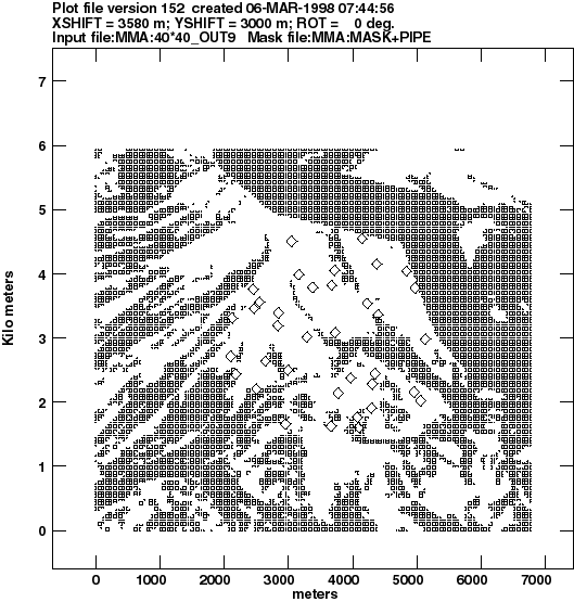
I applied the developed software to fit the 36 elements array to Chile site's topography.
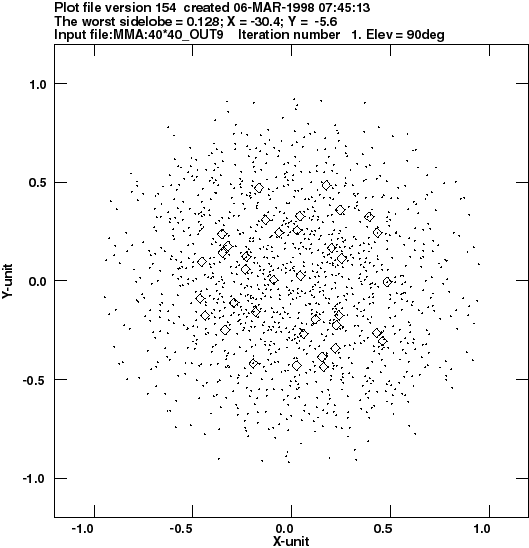
The achieved minimum worst sidelobe (0.128) practically coincides with the minimum (0.126) I had after optimization without topography constraint.
The result of the fitting is shown at figure (1). The relevant normalized configuration together with UV coverage is shown at figure
(2)
The given illustration of the optimization of 36 elements array can not be considered as a final solution. It demonstrates the ability of the developed software only. Another solution for the configuration can be found having additional constraint such as donuts for example.
References
- 1
- L.R. Kogan, MMA memo 171, 1997

Figure 1: Configuration fitted to the Chile site's topography. Size of the array is 3200 meters.

Figure 2: Configuration and UV coverage of the normalized array. Size of the original array is 3200 meters.

