W. D. Cotton1
May 8, 1998
This memo considers the effects of feed polarization type on the calibration of the MMA. Calibration of interferometers with circularly polarized feeds is only weakly affected by the polarization of typical calibrators whereas interferometers using linearly polarized feeds suffers from significant coupling of calibrator polarization and the determination of gains. This latter problem can be ignored if the calibrator is unresolved, both parallel handed correlations are always used and only total intensity is to be imaged. Uncorrected phase offsets between the two polarization channels of an interferometer with linear feeds will cause mutual corruptions of Stokes Q, U and V whereas this same calibration error in an interferometer with circularly polarized feeds rotates the apparent polarization angle of linear (Q+jU) polarization but does not otherwise corrupt the image.
Short term variations in polarization channel phase offsets mix total intensity and linear polarization in interferometers with linearly polarized feeds and total intensity and circular polarization with circularly polarized feeds. A system of monitoring this phase difference may be required.
Linearly polarized feeds require a wide range of parallactic angle for the determination of the calibrator linear polarization. This means that there can be no snapshot polarization projects with such a system. This is a fundamental limitation of the science that can be obtained with such an array. Calibration of the total intensity (Stokes' I) should be straight forward with either feed type but the details of the calibration of the polarization data differ.
In order to measure the polarization state of an astronomical signal a pair of orthogonally polarized feeds are generally used on all antennas in an interferometer array. On each baseline, or pair of antennas, all four cross correlation terms are measured. In practice, the feeds are sensitive to either orthogonal linear polarizations or right- and left-hand circular polarization. In the general case, it is necessary to have at least two of the four possible correlations (RR and LL or XX and YY for circular or linear feeds) even to measure the total intensity (Stokes I) of the astronomical source. This memo concerns issues related to the choice of linear or circularly polarized feeds for the Millimeter Array (MMA)
In an operating interferometer there will be time and antenna dependent variations in the arrival time of wavefronts from the source. The feeds will also not have a perfect response to the source polarization. The various atmospheric and instrumental effects will corrupt the data and must be estimated and removed from the data. This process is referred to as calibration.
The details of interferometric polarization calibration depend strongly on the polarization types of the detectors used to sample the incident wavefront. In addition, the residual effects of any uncorrected calibration errors also depend on the polarization of the feeds.
Interferometric calibration of connected element interferometers such as the proposed MMA usually involves observations of unresolved extragalactic sources. These objects are thought to radiate by the synchrotron mechanism which usually results in linear polarizations of a few percent to several tens of percent. On the other hand, the circularly polarized emission from these sources is generally under 0.1%. Since the calibrators used for radio interferometry are usually so weakly circularly polarized right-right (RR) and left-left (LL) cross polarizations can each be treated as estimates of the total intensity. This means both that the systems of right-circular and left-circular feeds can be calibrated independently and the determination of the time variable amplitude and phase calibration can be separated from the determination of the instrumental calibration.
The case is quite different for interferometers with linearly polarized feeds. Calibrator sources can generally not be considered to be unpolarized and no single correlation product is a good estimate of the total intensity. However, with some care, it is possible to partially separate the total intensity and polarization calibration
The polarization type of the feeds also affect the requirements for the accuracy of the calibration for a given level of image artifact in the different Stokes parameters. As a general rule, linear polarization (Stokes' Q and U) are less sensitive to calibration errors in interferometers with circular feeds than those with linear feeds whereas Q and U results are quite sensitive to errors in the calibration of systems with linear feeds. It is also the case that circular polarization (Stokes V) is less sensitive to calibration errors when observed with linear feeds than with circular feeds.
This discussion will use the ``Jones Matrix'' formalism of Schwab, 1979; Hamaker, Bregman and Sault, 1996; and Sault, Hamaker and Bregman, 1996 to evaluate the effects of the atmosphere, feeds and electronics on the received signals. This formalism factorizes the effects on the received signals into their antenna based components and the effect on the measured correlation products determined using the outer product of the antenna components.
The Jones matrix for a given antenna (i) with orthogonal feeds p and q can be factorized into a number of components arising from different physical effects:
![]()
The first factor, ![]() , is called the ``gain'' and is given by
, is called the ``gain'' and is given by
![]()
where ![]() and
and ![]() are complex factors for the signals
detected by the two feeds.
These factors represent the effects of the atmosphere and any
uncorrected effects due to the electronics.
are complex factors for the signals
detected by the two feeds.
These factors represent the effects of the atmosphere and any
uncorrected effects due to the electronics.
The second factor, ![]() , represents the imperfections in the
polarization response of the feeds.
This term is given by:
, represents the imperfections in the
polarization response of the feeds.
This term is given by:
![]()
where ![]() and
and ![]() are complex ``leakage'' term giving the
fraction of the orthogonal polarization ``leaking'' into a given feed.
This formalism is equivalent to the representation of the feeds in
terms of ellipticity and orientation but is somewhat more general.
are complex ``leakage'' term giving the
fraction of the orthogonal polarization ``leaking'' into a given feed.
This formalism is equivalent to the representation of the feeds in
terms of ellipticity and orientation but is somewhat more general.
The final factor represents the effects of the rotation of
an alt-az mounted antenna as seen by the source as the antenna tracks the source.
This rotation is known as the parallactic angle and is given by
![]()
where lat is the latitude of the antenna, dec is the source
declination, and ha is the source hour angle.
Antennas with equatorial mounts do not rotate as seen from the source
and thus have a constant parallactic angle (0).
The effect of parallactic angle in the received signal depends on the
polarization type of the feed:
![]() for linear or
for linear or
![]() for circular feeds
where
for circular feeds
where ![]() .
.
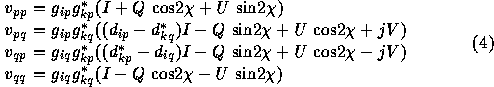
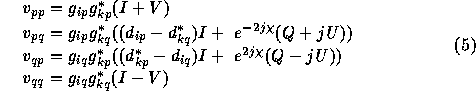
The response of an interferometer v = (qq,qp, pq, qq) is given by
the outer products of the Jones matrixes of the participating antennas:
![]()
where s is the true Stokes visibility vector (i, q, u, v).
The matrix S is a coordinate transformation from the Stokes coordinate
system to the system of the correlations and thus depends on the feed
type:
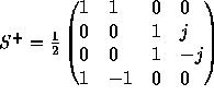 for linear or
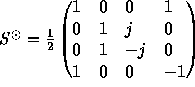 for circular.
This section discusses the determination of the G and D terms of Equation (1). Calibration of radio interferometers is usually done with synchrotron emitting compact extragalactic sources which have very weak circular polarization, typically 0.1% or less but have modest, few percent to tens of percent, linear polarization. As these source are physically small they tend to have variable total and polarized flux densities with time scales of months to years but in extreme cases show day-to-day variations. Since the polarization state of the phase calibration source is usually unknown it must be estimated jointly with the instrumental polarization. Fortunately, the variable parallactic angle of an alt-az antenna mount causes the source polarization to rotate on the sky whereas the instrumental polarization is fixed to the antenna. This effect allows observations over a range of parallactic angle to separate instrumental and source polarization although this separation is much cleaner using circularly polarized feeds than linear. See Sault, Hamaker and Bregman, 1996 for a more complete discussion of calibration strategy; note that this reference largely ignores the effects of parallactic angle.
This section concerns the use of a linearized approximation to the
feed model rather than a fully nonlinear model (and is unrelated to
the polarization to which the feed is sensitive).
Historically, most work with radio interferometers have used a linear
approximation to the response the the feed rather than the more
accurate description given in Equation (3).
Ignoring higher order terms in instrumental and source polarization or
their products leads to a linear approximation to the interferometer
response.
This approximation is applicable in the limit that the terms dropped
are small but ultimately will limit the accuracy of the calibration.
The linear approximation for parallel linear feeds on antennas i and
k is:
and for circular feeds:
Use of the linear approximation allows for faster computation and for at least partial separation of the determination of the g and d terms.
Equation (5) shows that the right-right (pp) and left-left (qq) cross correlations of an interferometer are sensitive to Stokes' I +/- V. This is well approximated by I for compact extragalactic radio sources allowing the separation of the calibration of the right- and left-circularly polarized systems from each other and from the instrumental polarization calibration (d terms).
The usual technique is to first determine the time variable amplitude
and phase corrections (![]() and
and ![]() in Equation (1)) and then
correcting and time averaging the data before determining the source
and instrumental polarization parameters (
in Equation (1)) and then
correcting and time averaging the data before determining the source
and instrumental polarization parameters (![]() and
and ![]() in
Equation (1)).
Equation (5) showss that the source and instrumental contributions
to the
in
Equation (1)).
Equation (5) showss that the source and instrumental contributions
to the ![]() and
and ![]() correlations are both complex values that
rotate with respect to each other with changing parallactic angle.
correlations are both complex values that
rotate with respect to each other with changing parallactic angle.
The linear approximation leads to errors in the usual case of imperfect feeds and polarized calibrators. For the ultimate in calibration a full nonlinear feed model should be used which eliminates the simplifying assumptions and requires a joint solution for amplitude, phase and polarization terms.
If there is a residual error in the p-q phase offset (called the R-L phase offset on the VLA and VLBA) Equation (5) indicates that this results in a rotation of the linear polarization between Q and U. This is equivalent to a rotation of the apparent polarization angle of the source. If this phase offset is constant then the linear polarization images are uncorrupted but give an incorrect polarization angle.
The cross correlations of an interferometer with linear feeds
(equation (4)) measure Stokes I +/- a linear polarization term which
depends on the parallactic angle.
For a point source at the phase center (i.e. a calibrator source) the
term ![]() is real and thus does not
affect the phase of the interferometer response.
Furthermore, this term is the same for all antennas (assuming a common
is real and thus does not
affect the phase of the interferometer response.
Furthermore, this term is the same for all antennas (assuming a common
![]() ) and its effect is a scaling of all pp or qq responses.
If this term is assumed to be zero and the g terms determined
independently for the q and p systems the derived phases of the
g will be correct but amplitudes of the
) and its effect is a scaling of all pp or qq responses.
If this term is assumed to be zero and the g terms determined
independently for the q and p systems the derived phases of the
g will be correct but amplitudes of the ![]() and
and ![]() will be in
error by the ratio:
will be in
error by the ratio:
![]()
If these gains are applied to the pp and qq correlations and used
to derive Stokes I then the gain errors will cancel.
Note: this only applies to a point-like calibrator source and does not
apply to self calibration of an extended source.
When polarization results are also desired, further refinement of the calibration is required. The gains (g terms) must be corrected for the effects of the actual calibrator values of Q and U. A range in the parallactic angle of the observations does not lead to a clean separation of the source and instrumental polarization as in the case of circularly polarized feeds, in particular, the circular polarization is unaffected by parallactic angle and cannot be separated from the instrumental polarization. For these reasons, using an additional calibration source of known polarization (preferable unpolarized) may be necessary to determine the instrumental polarization (d terms).
If the calibration gains are initially determined using the assumption
that the calibrator has no linear polarization then the pp and qq
correlations with these gains applied will be systematically in error
and consistent with no polarization.
However, the gain errors cancel when applied to the pq and qp
correlations.
If the instrumental polarization is corrected then from equation (4) the
real part of the pq and qp correlations is ![]() .
Observations over a range of parallactic angle are then required to
separate Q and U.
This implies that even for a snapshot observation the calibration
observations must continue over an extended period (potentially many
hours).
.
Observations over a range of parallactic angle are then required to
separate Q and U.
This implies that even for a snapshot observation the calibration
observations must continue over an extended period (potentially many
hours).
A further complication is determining the phase offset between the
p and q systems which in the scheme outlined above will be
unconstrained.
Equation (4) indicates that an uncorrected phase difference will cause
a rotation between (![]() and jV.
Such an error will seriously degrade the calibration and corrupt any
resultant polarized results.
This phase offset can be determined by observations of a sufficiently
strongly polarized source.
However, it is impractical for frequent observations of such a
calibrator and direct electronic monitoring of the the p-q phase
difference may be required to ensure the required stability.
and jV.
Such an error will seriously degrade the calibration and corrupt any
resultant polarized results.
This phase offset can be determined by observations of a sufficiently
strongly polarized source.
However, it is impractical for frequent observations of such a
calibrator and direct electronic monitoring of the the p-q phase
difference may be required to ensure the required stability.
As in any system, errors in the calibration of interferometer data will degrade the results. The details of which measured Stokes parameters are degraded by what calibration error depends on the polarization type of the feeds. The most important relevant calibration items for this discussion are the ``leakage'' terms describing a feeds' response to a signal and the phase corruption of the signal by the atmosphere and electronics. The leakage terms are generally stable and are usually assumed constant over the course of a single observations (hours in duration). On the other hand, phase fluctuations can be quite rapid with time scale of seconds at millimeter wavelengths. Both of these effects are calibrated using measurements of astronomical calibration sources.
Deviations of the antenna feeds from perfect polarization response will, if uncorrected, cause artifacts in the results derived from such data. Most sources are weakly polarized so the strongest instrumental artifacts are seen in polarized light (Stokes' Q, U or V) although in high dynamic range results the total intensity (Stokes' I) can be affected as well.
The results of imaging data with uncorrected instrumental polarization is the introduction of artifacts in the vicinity of total intensity emission (see Leppänen 1995). At centimeter wavelengths the instrumental linear polarization terms are generally a few percent resulting in errors in polarizations images on the order of a percent of the total intensity, if left uncorrected. Current calibration practice generally results in a factor of 10 or more reduction in the level of linearly polarized artifacts. This level of artifact is generally acceptable for objects with polarizations ranging from a few percent to a tens of percent linear polarization. The normal astronomical calibration should adequately determine the instrumental polarization for either type of feed.
The phase difference introduced by the atmosphere and electronics between the two polarization channels of a given antenna is particularly a problem as it is difficult to measure using astronomical calibrators. The atmospheric contribution to the polarization phase difference is due to Faraday rotation in the ionosphere; this effect increases with the square of the wavelength and can generally be ignored at millimeter wavelengths. Phase fluctuations arising from the electronics can, in principle, be measured.
An instrumental phase calibration system widely used with VLBI and the Australia Telescope is to inject tones into the feeds and measure the phase of these tones after all of the active elements in the electronics. There may still be a phase difference between the two polarizations but as this will be due to the mechanical details of the injection of the phase calibration tones it should be quite stable and measurable. Such a phase calibration system cannot determine the corrupting effects of the atmosphere which must still be determined using celestial sources.
At millimeter wavelengths there are technical problems with generating suitable tones at the RF and the phase calibration tones may be injected into the IF. This scheme has the disadvantage that the effects of elements of the signal processing path are not monitored.
The effects of calibration errors on images derived from an array are more difficult to predict that the effects on a single interferometer. The nature of image artifacts depends on the commonality of the errors among the various antennas. Completely independent errors will tend to reduce the overall impact.
The following sections discuss the effects of calibration errors for systems with linear and circular feeds.
Phase errors of individual feeds are measured with the normal astronomical calibration although the phase accuracy is limited by the SNR of the measurements of the calibrator and their limited frequency in time. An overall offset between the phases of the p and q gains cannot be determined from astronomical measurements except for observations of a strongly polarized source of known polarization; such sources are rare and might be difficult to find at millimeter wavelengths. A systematic p-q phase offset will cause a rotation of the source response in the Q - U plane; this will not corrupt the polarized images and preserves polarized intensity but rotates the apparent polarization angle of sources. A suitable instrumental phase calibration system would substantially reduce this problem.
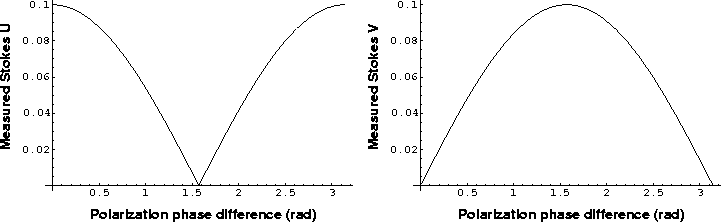
Figure 1: Simulated Stokes' U and V responses to a source with ten percent U and no V component as measured on an interferometer at zero parallactic angle with linear feeds and with a range of p-q phase offsets.
The effects of any p-q phase differences are more serious for interferometers with linear feeds; these differences cannot be determined from pp and qq measurements alone or from any measurements of an unpolarized source. The usual astronomical calibration will align the phases of each of these systems to have the p-q phase offset of the ``reference antenna'' which may or may not be stable in time. The effect of an over all p-q phase offset is to rotate the source response between linear and circular polarization. The effect of this phase offset on a source with ten percent U and zero V polarization at a parallactic angle of zero is shown in Figure 1. According to this Figure, Stokes' V is contaminated by 2% of the linear polarization per degree of p-q phase difference. This coupling is quite undesirable as the Stokes' U and V components arise from different physical effects in the emitting region. Even if the p-q phase difference is stable in time both the linear and circular polarization data will be corrupted. A suitable instrumental phase calibration system would substantially eliminate this problem or at least lead to a system with a stable p-q phase offset.
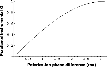
Figure 2:
Simulated Stokes' Q response to a 1 Jy source as measured on an
interferometer at zero parallactic angle with linear feeds and with a
range of p-q phase offsets.
The previous section discussed the effects of an overall p-q
phase offset; short term fluctuations on individual antennas have
other effects.
An offset in the p-q phase difference in a single antenna of an
interferometer employing linear feeds will cause a rotation between
the source total intensity (Stokes' I) and the linear polarization.
This effect is shown for zero parallactic angle in Figure 2.
A phase difference of one degree results in an instrumental
polarization of ![]() 1%.
Note: this only applies to short term fluctuations of the p-q phase
difference; longer term differences will be removed by the
astronomical calibration.
Since these fluctuations are variable and independent among antennas,
the averaging in a typical synthesis will reduce their effects.
1%.
Note: this only applies to short term fluctuations of the p-q phase
difference; longer term differences will be removed by the
astronomical calibration.
Since these fluctuations are variable and independent among antennas,
the averaging in a typical synthesis will reduce their effects.
Most sources have total intensities at least an order of magnitude higher that the linear polarization so a variable p-q phase difference will increase the noise in the linear polarization response. As noted above, most of the variations in the p-q phase difference will be from the electronics of the telescope and hence can be measured and removed. If the time variable corruption of the linear polarization by the total intensity is to be kept below 1% then the relative phases of the p and q must be known to within 1 degree on the relevant time scales.
The differences between linearly and circularly polarized feeds is largely in the derivation of images in polarized emission. The assumption of no circular polarization in calibration sources is quite good for the extragalactic sources generally used for calibration. These sources frequently have at least a few percent linear polarization which will affect the calibration of interferometers with linearly polarized feeds. This problem can be ignored if 1) the calibration source is unresolved, 2) both the qq and pp correlations are used to derive the Stokes I and 3) only total intensity (Stokes I) polarization is used. If the data are to be used to study the polarized emission then a correction to the derived gains must be applied to account for the calibrator polarization. Determining the Q and U components of the calibrator polarization from linear feeds requires observations over an extended range of parallactic angle (time). This problem results in a limitation on the science of an array with linearly polarized feeds: no polarization calibration using ``snapshot'' observations. Snapshot observations can be imaged but calibration requires more extensive observations.
The serious impact of a phase offset between the two parallel-hand correlations of interferometers of any feed type and the difficulty of calibration using astronomical sources suggests that an electronic phase calibration system for the electronics is very desirable. The effects of this calibration error are more serious for systems with linearly polarized feeds as even a constant offset will corrupt all linear polarization data. A variable phase difference can increase the noise in linearly polarized data. The effect of a constant offset on an interferometer with circularly polarized feeds is to rotate the apparent polarization angle but the derived source fractional polarization is unaffected.
The following are lists of arguments for and against circularly or linearly polarized feeds.
I would like to thank Fred Schwab for assistance and many helpful discussions.
Hamaker, J.P., Bregman, J.D., Sault, R.J. 1996, Astron. Astrophys. Suppl., 117, 137.
Leppänen, K. 1995, ``22 GHz polarimetric imaging with the Very Long Baseline Array'', PhD Thesis, Helsinki University of Technology.
Sault, R.J., Hamaker, J.P., Bregman, J.D.,1996 Astron. Astrophys. Suppl., 117, 149.
Schwab, F., 1979, VLA Computer Memorandum No. 154.